Cryostat

a cryostat and surface technology, applied in the field of cryostats, can solve the problems of increasing difficult to achieve the effect of effective suppression of so as to achieve the effect of effectively suppressing water condensation on the surface, and reducing the size of cryostats

Active Publication Date: 2011-07-14
JAPAN SCI & TECH CORP
View PDF5 Cites 5 Cited by
  • Summary
  • Abstract
  • Description
  • Claims
  • Application Information

AI Technical Summary

Benefits of technology

[0026]The cryostat of the present invention uses a sealing material having a water vapor transmission rate of 30000 cc·cm2·mm·sec·cm Hg×1010 or lower as a sealing material for sealing the optical windows from the inside of the optical path tubes. This can prevent the entry of water vapor from outside, and effectively suppress water condensation on the surface of the cell. For example, even when measurement is performed under atmospheric pressure, water condensation on the surface of the cell can be effectively prevented. Therefore, the cryostat of the present invention need not be particularly provided with a mechanism for maintaining vacuum or the like, and its internal structure can thus be simplified. As a result, a reduction in the size of the cryostat can be realized. The cryostat of the present invention can prevent the entry of water vapor even when optical measurement is performed for a long period of time, and maintain significant effects in suppressing water condensation.
[0027]In the cryostat of the present invention, the diameters of the first optical window for allowing a light beam to enter the cell housing and / or the second optical window for allowing the light beam having passed through the cell housing to output are set to 16 mm or larger, and thus distortion in the optical windows due to heat and pressure can be prevented. As a result, optical measurement with high accuracy (for example, measurement of CD spectra) is facilitated.
[0028]Furthermore, the aperture window is placed outside the first optical window. Accordingly, incident light can be restricted, and optical measurement can be carried out more favorably.
[0029]Materials containing an ethylene fluoride resin are employed as the first and second optical path tubes within the cryostat of the present invention. Accordingly, moisture in the optical path tubes can be favorably removed, and water condensation on the surface of the cell can be further prevented.
[0030]A gas flow path is provided for feeding a gas to the first optical path tube and / or second optical path tube in the cryostat of the present invention. Accordingly, moisture inside the cryostat can be efficiently removed prior to the optical measurement. As a result, water condensation (fog) on the surface of the cell can be further prevented.
[0031]The cryostat of the present invention can be used as a cryostat for various optical measuring devices. In particular, the cryostat of the present invention can be favorably used as a cryostat for a circular dichroism spectrometer. According to the cryostat of the present invention, even when the cell is cooled to −80° C. or lower, for example, to about −165° C., water condensation on the surface of the cell can be effectively suppressed. Accordingly, a circular dichroism spectrometer comprising the cryostat of the present invention enables CD spectrum measurement at very low temperatures (for example, −165° C.).

Problems solved by technology

When an optical measurement is performed for a long period of time, there is a problem such that water vapor flows into the cryostat; consequently, water condenses on the surface of the cell, and the optical measurement cannot be performed effectively.
Therefore, the internal structure becomes complicated, which is a cause of an increase in the size of cryostats.
In addition, when the inside of the cryostat is under vacuum, optical windows may be distorted, and therefore the CD spectra cannot be accurately measured in some cases.

Method used


Image

  • Cryostat
  • Cryostat
  • Cryostat

Examples


examples

[0080]Examples and Comparative Examples will be shown below to more specifically describe the present invention. However, the present invention is not limited to the Examples.

example 1

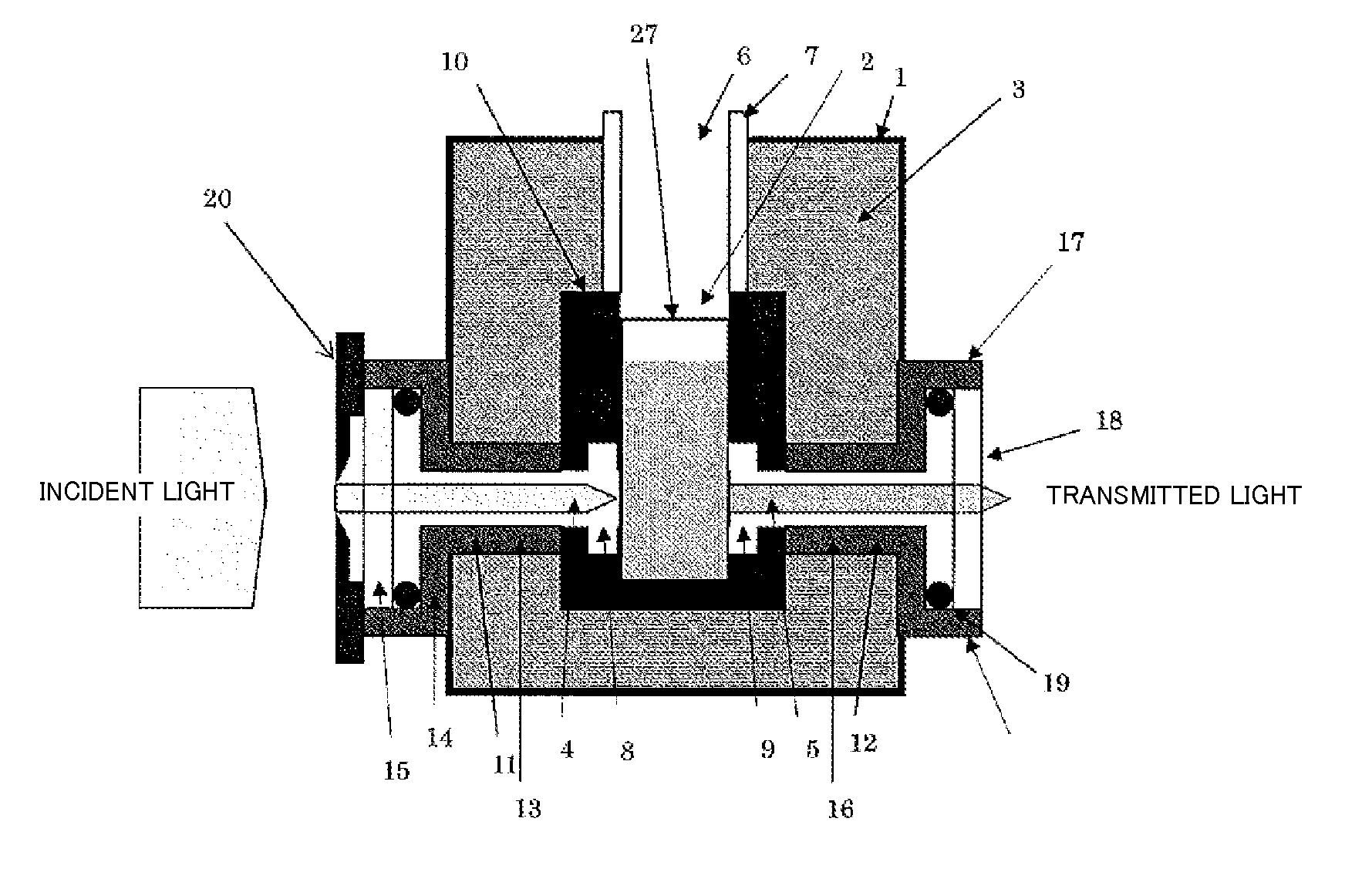
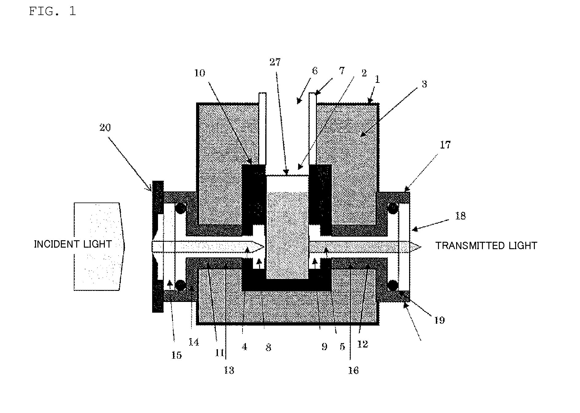
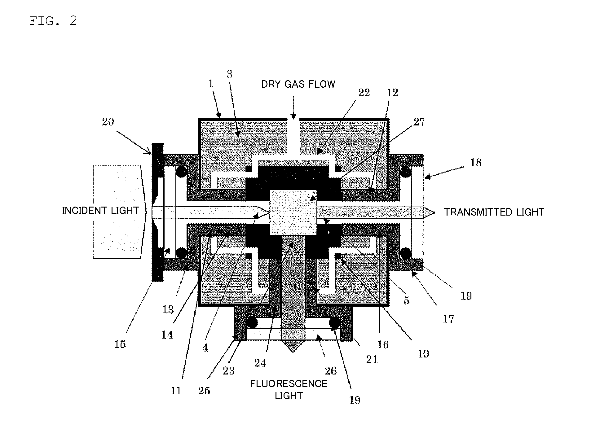
[0081]A cryostat having the structure shown in FIG. 1 was assembled.

[0082]A composition containing the components described in Table 1 below was used for a sealing material 19.

TABLE 1Fluorine-containing polymer (product name “Dyneon LTFE100g6400X”, manufactured by Sumitomo 3M Limited)Thermal carbon black N990 (MT Carbon)50gZinc oxide5gPeroxide (product name “DBPH-50”; manufactured by2.5gVarox)Cross-linking agent (manufactured by TAIC; 72%)2.5gLubricant (product name “WS 280”; manufactured by0.5gStruktol)

[0083]The water vapor transmission rate of the above fluorine-containing polymer (Dyneon LTFE 6400X) is 520 cc·cm2·mm·sec·cm Hg×1010.

[0084]The diameters of the light inlet 4, light outlet 5, first optical path tube 11, second optical path tube 12, and fluorescence light exit port 23 provided in the heating / cooling block 10 were all 10 mm.

[0085]The first optical window 15, second optical window 18, and third optical window 26 used were all made of synthetic quartz, and had a round sha...

example 2

[0089]A cryostat having the structure shown in FIGS. 3 and 4 was assembled.

[0090]More specifically, a cryostat was assembled in a manner similar to those in FIGS. 1 and 2, except that the diameters of the first optical window 15, second optical window 18, and third optical window 26 were all 15 mm; the aperture window 20 was not provided; the diameters of the first cavity 8, second cavity 9, and third cavity (not shown) were all 18 mm; and the gas flow path 22 was not provided.


PUM

PropertyMeasurementUnit
diametersaaaaaaaaaa
temperaturesaaaaaaaaaa
diametersaaaaaaaaaa

Abstract

Provided is a cryostat that can effectively prevent water condensation on the surface of a cell.
The cryostat includes: a casing having an inlet port and exit port; a cell housing provided in the casing; a temperature controller for adjusting the temperature of the cell; a first optical path tube for guiding a light beam from the inlet port of the casing to the cell housing; a second optical path tube for guiding the light beam having passed through the cell housing to the exit port of the casing; first and second optical windows disposed at openings, exposed to the outside, of the first and second optical path tubes, respectively; and sealing materials having a water vapor transmission rate of 30000 cc·cm2·mm·sec·cm Hg×1010 or lower, disposed at the peripheries of the first and second optical windows to seal the first and second optical path tubes.

Description

TECHNICAL FIELD[0001]The present invention relates to a cryostat.BACKGROUND ART[0002]Optical measuring devices such as circular dichroism spectrometers, ultraviolet-visible spectrophotometers, and spectrofluorimeters are sometimes provided with cryostats for accommodating a cell. A cell accommodated in a cryostat is irradiated with a light beam to measure a spectrum, thereby allowing the chirality, structure, and the like of a compound to be determined (Non-patent Literature 1).[0003]When an optical measurement is performed for a long period of time, there is a problem such that water vapor flows into the cryostat; consequently, water condenses on the surface of the cell, and the optical measurement cannot be performed effectively. In order to solve such a problem, operations for evacuating the cryostat and like operations have been conventionally performed.[0004]However, in order to evacuate the cryostat, a special mechanism for maintaining vacuum or the like must be placed therein...

Claims


Application Information

Patent Timeline
Patent Type & Authority Applications(United States)
IPC IPC(8): G01N21/01F25B19/00
CPCG01N21/0332G01N2021/158G01N21/19G01N21/15
Inventor INOUE, YOSHIHISAOKAMOTO, KIDOWADA, TAKEHIKONAKAGAWA, TATSUO
Owner JAPAN SCI & TECH CORP
Why Eureka
Try Eureka