Method for making a part made of a composite material with a metal matrix

a metal matrix and composite material technology, applied in the field of metal matrix composite material making a part, can solve the problems of limited mass reduction, fragile ceramic charge placement, and condition the behavior of the composite structure, and achieve the effect of reducing the risk of porosity and improving the homogeneity of the metal matrix

Inactive Publication Date: 2011-07-14
AIRCELLE
View PDF3 Cites 9 Cited by
  • Summary
  • Abstract
  • Description
  • Claims
  • Application Information

AI Technical Summary

Benefits of technology

[0020]Thus, by providing previously coated fibers on a preform, it is possible to make parts with complex shapes from composite material with a metal matrix while precisely controlling the orientation of the fibers, their spacing and distribution.
[0021]Moreover, the fibers being previously coated, the metal coatings of the different fibers can be easily brought into contact, which imparts better homogeneity of the metal matrix after heat treatment thereof and decreases the risks of porosity and of zones without metal that must be corrected in a subsequent step.
[0023]Advantageously, the method comprises a step for compression of the molten metal between the mold and the preform. However, due to the possibility of bringing the metal coatings of the fibers into close contact, the compression forces making it possible to ensure good diffusion of the metal after melting thereof are reduced.
[0025]Advantageously, the compression step is done by heat expansion of the preform, in particular by replacing a hot isostatic compaction (HIC). This is made possible by the fact that the necessary compression forces are greatly reduced.

Problems solved by technology

Thus, for fine structures, the mass decrease is limited by the manufacturing conditions.
The placement of ceramic charges is delicate and conditions the behavior of the composite structure.
However, the forming of these materials to form the final piece is delicate.
The forming of the plates to produce the final piece, such as a jet nozzle for example, remains difficult.
This method is, however, limited to parts having a symmetry axis of revolution, the mandrel being driven in rotation.
The mandrel having to be driven in rotation, such a method has limitations in the production of parts with large dimensions, such as nozzles, for example.
Moreover, the quantity of metal on the fibers, their spacing as well as the final porosity are difficult to control.
The orientation of the fibers also cannot be controlled since they must be wound around the mandrel.

Method used


Image

  • Method for making a part made of a composite material with a metal matrix
  • Method for making a part made of a composite material with a metal matrix

Examples


Embodiment Construction

[0035]A method according to the invention is used to make a part from a composite material with a metal matrix, such as a turbojet engine nozzle or a nozzle portion, for example.

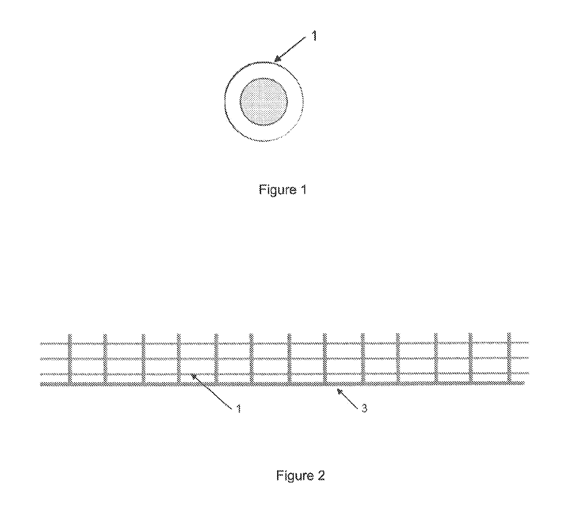
[0036]According to the inventive method, an assembly of fibers 1 intended to make up a reinforcing charge of the composite material with a metal matrix is previously coated with the considered metal alloy or metal.

[0037]The fibers 1 can be in several forms and several materials.

[0038]Examples of component materials of the fibers 1 were provided above.

[0039]The fibers 1 can assume the form of long fibers, woven bedding, strips and charged strips, for example.

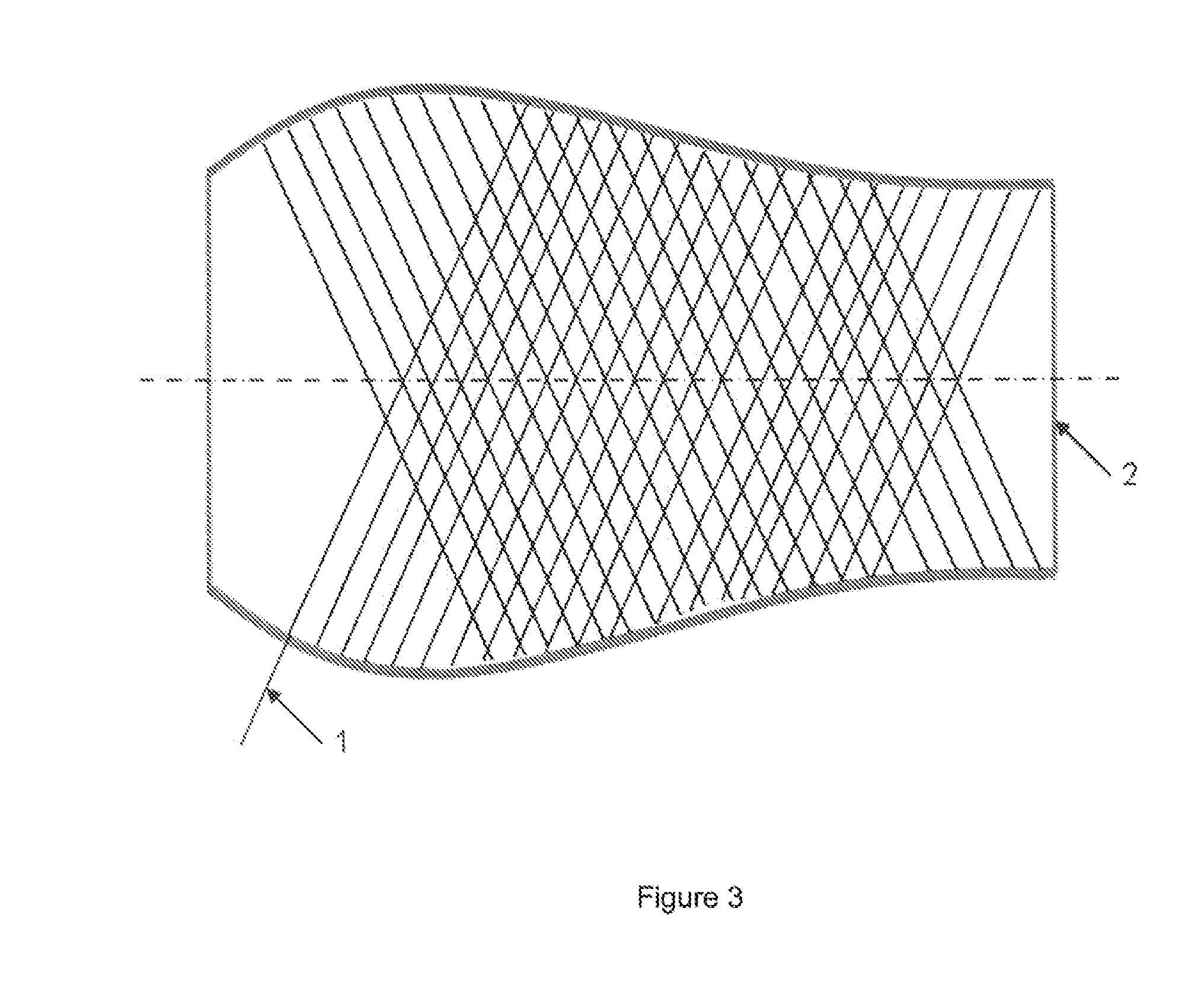
[0040]The reinforcing fibers 1 are arranged on a preform 2 of the final part.

[0041]Long fibers 1 may be positioned by winding on the preform 2.

[0042]Short fibers or woven strips may be positioned by stacking on the preform.

[0043]The coating of the fibers 1 may be done by passing the fibers in a bath of the desired metal or alloy.

[0044]The coated fibers 1 ...


PUM

PropertyMeasurementUnit
temperaturesaaaaaaaaaa
temperatureaaaaaaaaaa
chargesaaaaaaaaaa

Abstract

The invention relates to a method for making a part made of a composite material with a metal matrix, characterised in that the method includes the steps of: providing, on a preform of the part to be made, at least one assembly of reinforcing fibres, said fibres being previously coated with at least one metal or metal alloy; heating the assembly to a temperature sufficient for diffusing the metal particles surrounding the fibre; after cooling, releasing the part made of the preform and withdrawing the latter.

Description

TECHNICAL FIELD The present invention relates to a method for making a part made from a composite material with a metal matrix.BACKGROUND[0001]The high temperatures output from a turbojet engine require the use of metal materials resistant to high temperatures. In particular for temperatures above 600° C., the use of nickel-based alloys becomes necessary to bear the thermal and mechanical loads. Indeed, the mechanical aspect of most other metal alloys is greatly decreased in these temperature ranges.[0002]One of the main drawbacks of these nickel-based alloys, such as Inconel 718, Inconel 625, or Waspaloy™, is a high density. Thus, for fine structures, the mass decrease is limited by the manufacturing conditions.[0003]Mass gain is a major objective in aeronautic construction and there is therefore always a need for materials combining a low density with high thermal and mechanical properties.[0004]One solution is to use composite materials with a metal matrix.[0005]The addition of c...

Claims


Application Information

Patent Timeline
Patent Type & Authority Applications(United States)
IPC IPC(8): B32B5/16B32B37/02B32B37/06B32B37/10B32B38/00B32B15/00
CPCB22F2998/10C22C47/20C22C49/14Y10T156/10Y10T428/12493C22C47/02Y10T442/2033
Inventor RUCKERT, GUILLAUMELE DOCTE, THIERYANDRE, VIJAYSZKOLNIK, EDMOND
Owner AIRCELLE
Why Eureka
Try Eureka