Plant control apparatus

a technology of plant control and control apparatus, which is applied in the direction of electrical control, process and machine control, instruments, etc., can solve the problems of power reduction, control delay, and inevitably the maximum cylinder pressure of control delay,

Active Publication Date: 2011-07-14
HONDA MOTOR CO LTD
View PDF4 Cites 74 Cited by
  • Summary
  • Abstract
  • Description
  • Claims
  • Application Information

AI Technical Summary

Problems solved by technology

However, when the value of the cylinder pressure is detected by the cylinder pressure sensor as described above and the maximum cylinder pressure is controlled to be equal to or lower than the upper limit by using a feedback control algorithm, a control delay inevitably occurs in the maximum cylinder pressure because the ignition (injection) timing that is calculated based on the present combustion cycle is used in the next combustion cycle.
Therefore, for example, the maximum cylinder pressure may temporarily exceed the upper limit, or conversely, the power may decrease because control may be performed so as to unnecessarily reduce the maximum cylinder pressure.
Such phenomena, which are against the driver's intention, often occur in a transient driving state.
However, the same problem related to a control delay may also arise when performing feedback control so as to limit a control variable of an engine to be equal to or lower than an upper limit.

Method used


Image

  • Plant control apparatus
  • Plant control apparatus
  • Plant control apparatus

Examples


first embodiment

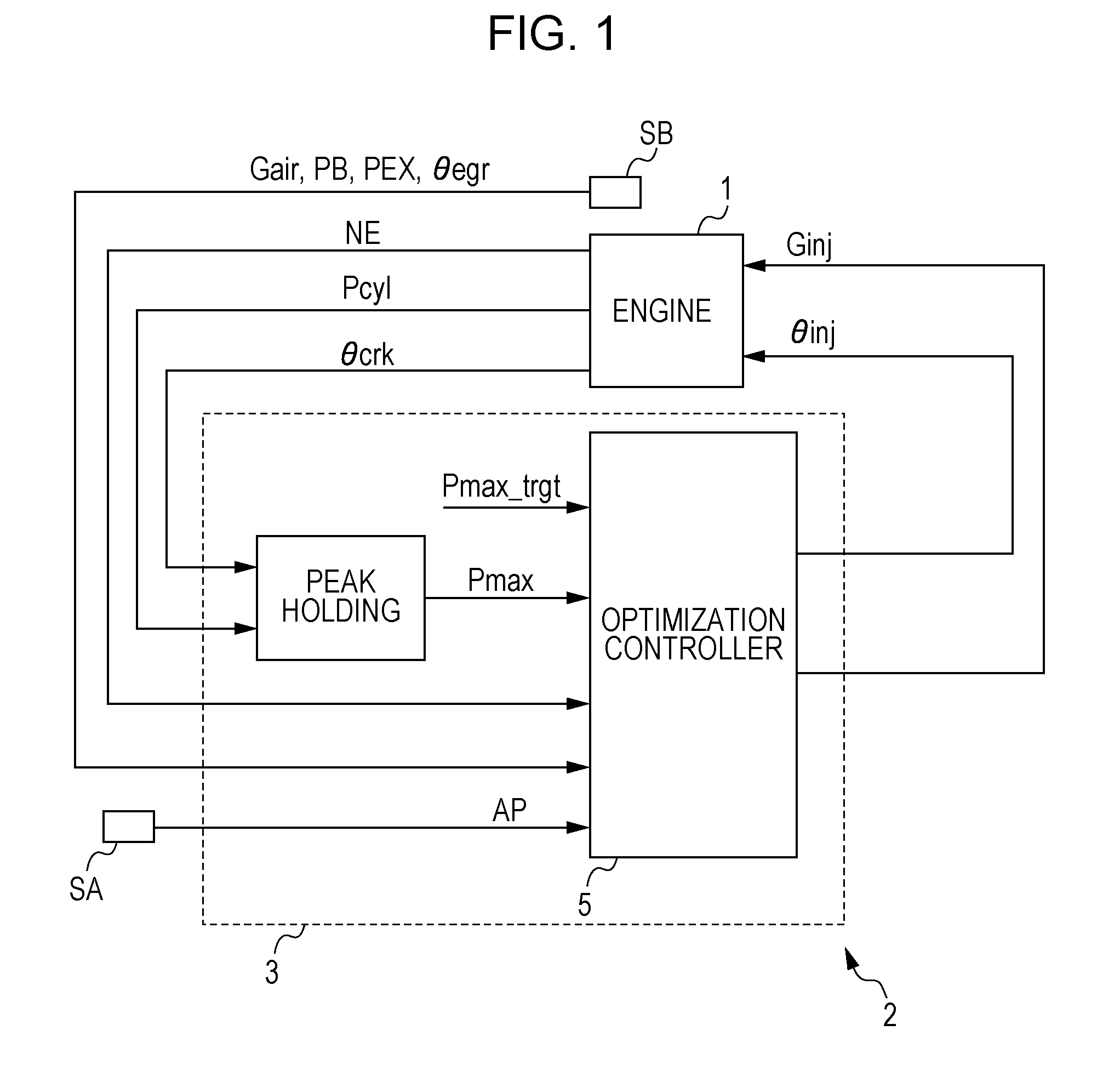
[0043]Hereinafter, a first embodiment of the present invention will be described with reference to the drawings. FIG. 1 is a block diagram of an internal combustion engine 1 (hereinafter referred to as an engine), which corresponds to a plant, and a control device 2 for the engine 1 according to the present embodiment.

[0044]The engine 1 is a lean burn gasoline or diesel engine that is mounted in a vehicle (not shown). The engine 1 has a plurality of cylinders. For each cylinder, a fuel injection valve for injecting fuel into the combustion chamber of the cylinder is provided.

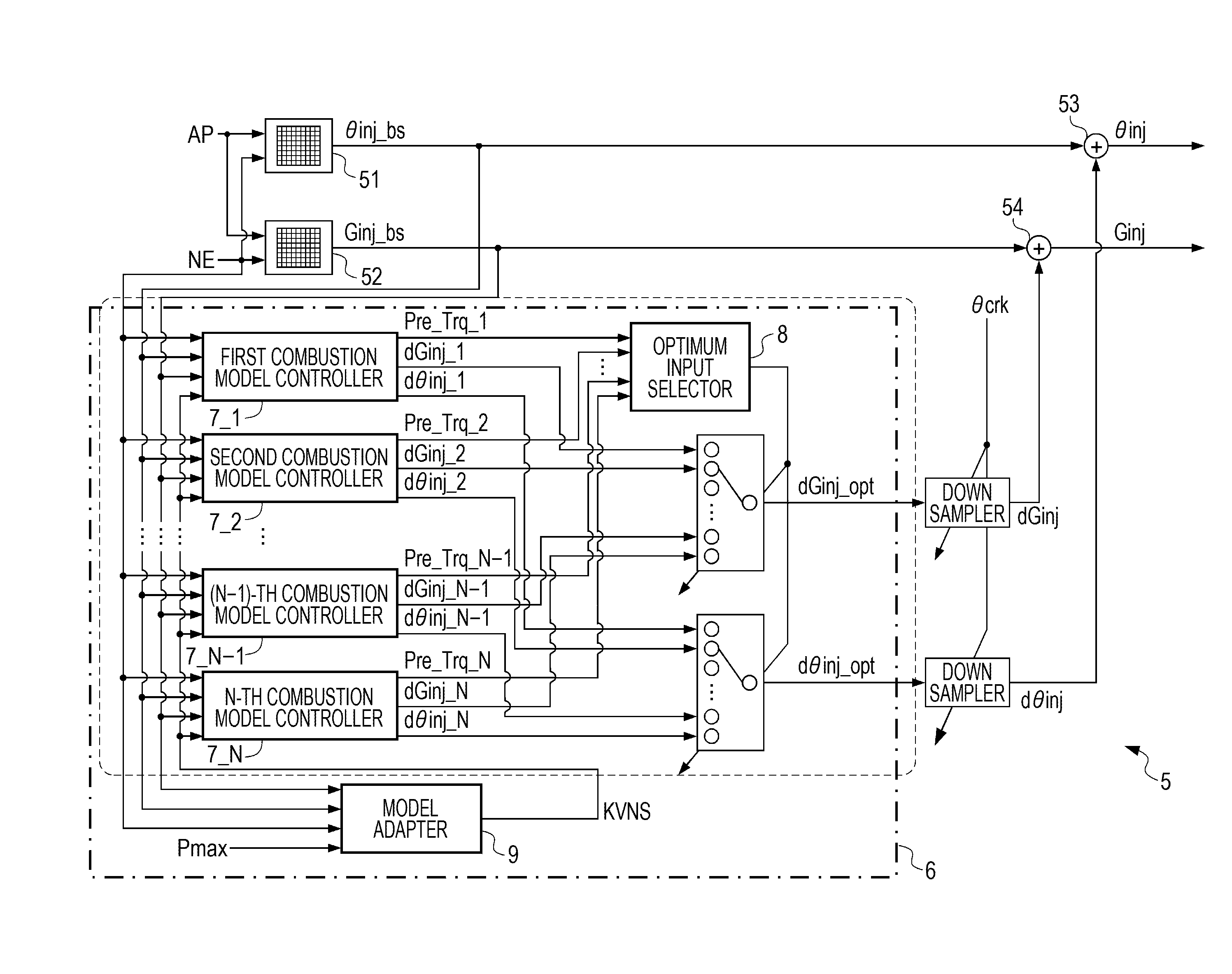
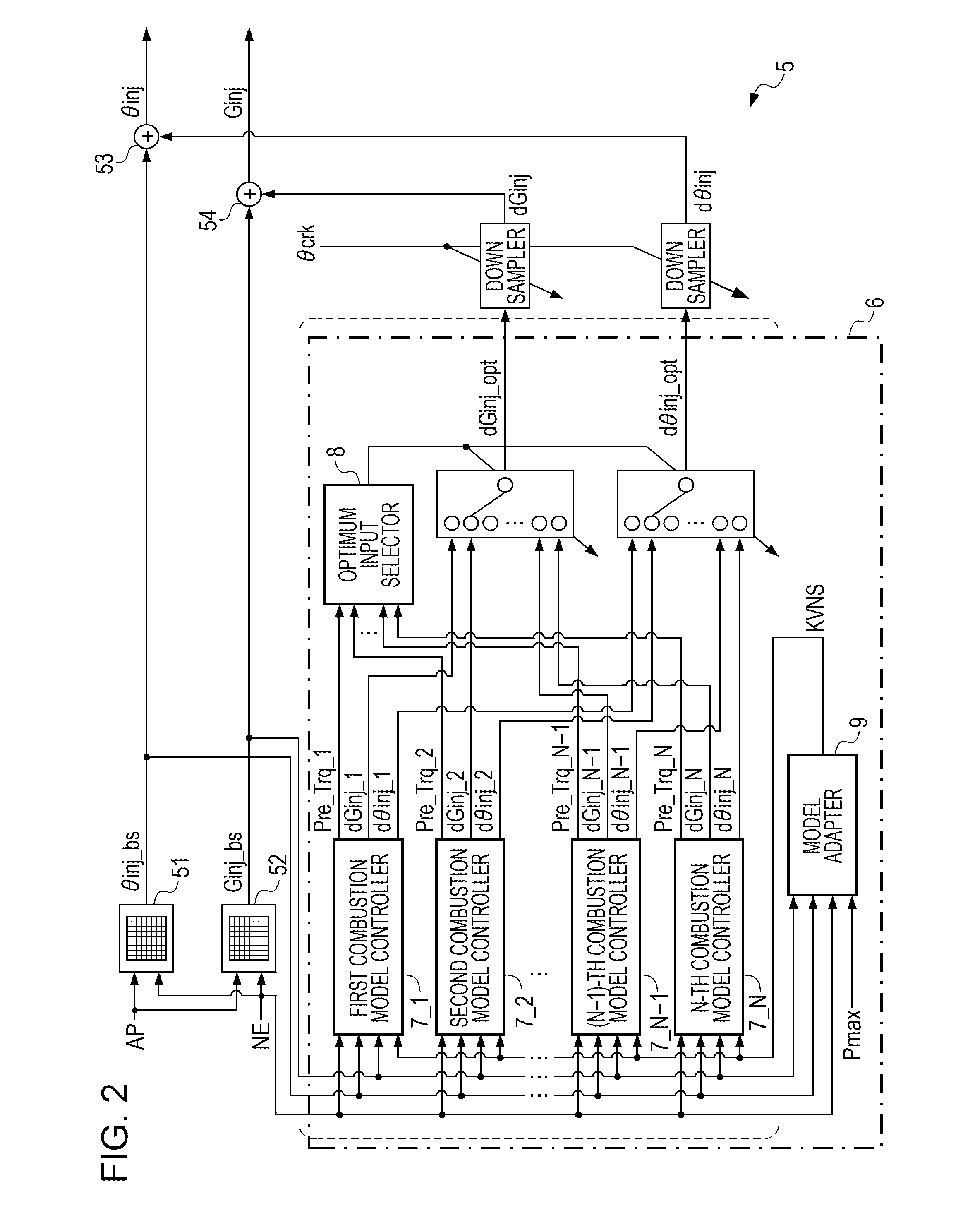
[0045]The control device 2 includes a crank angle sensor (not shown), a cylinder pressure sensor (not shown), and an electronic control unit 3 (hereinafter referred to as an ECU). The crank angle sensor detects the rotation angle of the crankshaft of the engine 1. The cylinder pressure sensor detects the cylinder pressure of the engine 1. The ECU 3 determines a fuel injection quantity Ginj and a fuel injection t...

second embodiment

[0187]Next, a second embodiment of the present invention will be described with reference to the drawings. In the following description of the second embodiment, the elements the same as those of the first embodiment will be denoted by the same numerals, and the description of such elements will be omitted or shortened.

[0188]FIG. 23 is a block diagram of the engine 1 (i.e., a plant) and a control device 2A according to the present embodiment. In the present embodiment, the control device 2A includes an ECU 3A including an optimization controller 5A. In order to control the maximum cylinder pressure Pmax to be equal to or lower than the target maximum cylinder pressure Pmax_trgt, the optimization controller 5A determines the fuel injection quantity Ginj, which is input to the fuel injection valve of the engine 1 at each combustion cycle, and the fuel injection split ratio Rinj for the main injection, which is input at each combustion cycle, to be at optimum values.

[0189]If the main i...

third embodiment

[0193]Next, a third embodiment of the present invention will be described with reference to the drawings. In the following description of the third embodiment, the elements the same as those of the first embodiment will be denoted by the same numerals and the description of such elements will be omitted or shortened.

[0194]FIG. 26 is a block diagram of an engine 1 (i.e., a plant) and a control device 2B for the engine 1 according to the present embodiment. The control device 2B includes an NOx sensor (not shown), a crank angle position sensor (not shown), and an ECU 3B. The NOx sensor detects the amount of NOx (hereinafter referred to as feed NOx) exhausted from the engine 1. In the present embodiment, the ECU 3B includes an optimization controller 5B. The optimization controller 5B determines the fuel injection quantity Ginj, which is input to the fuel injection valve of the engine 1 at each combustion cycle, and the fuel injection split ratio Rinj for main fuel injection, which is ...


PUM


Abstract

A plant control apparatus includes a plant model and a control input determining device. The plant model estimates a control variable of a plant based on an input including a control parameter to adjust a first control variable of the plant. The control input determining device is configured to correct a temporary value of the control parameter so that a first control variable model value satisfies a predetermined constraint. The control input determining device is configured to determine a control input for the plant based on the temporary value of the control parameter that has been corrected. The first control variable model value is defined as an estimated value of the first control variable calculated by the plant model when the temporary value of the control parameter is input to the plant model.

Description

CROSS-REFERENCE TO RELATED APPLICATIONS[0001]The present application claims priority under 35 U.S.C. §119 to Japanese Patent Application No. 2010-006187, filed Jan. 14, 2010, entitled “Plant Control Apparatus”. The contents of this application are incorporated herein by reference in their entirety.BACKGROUND OF THE INVENTION[0002]1. Field of the Invention[0003]The present invention relates to a plant control apparatus.[0004]2. Description of the Related Art[0005]Existing control methods for a gasoline engine and a diesel engine set the optimum ignition timing and the optimum fuel injection timing in accordance with an engine speed, an air-fuel ratio, and the like so as to maximize the performance of the engine. It is known that the ignition timing and the injection timing are correlated with the maximum value of the cylinder pressure in each combustion cycle (hereinafter referred to as the maximum cylinder pressure). In order to prevent overloading of the engine, the maximum cylinde...

Claims


Application Information

Patent Timeline
Patent Type & Authority Applications(United States)
IPC IPC(8): F02D41/30F02D28/00
CPCF02D35/023F02D35/024F02D41/1401F02D41/1405F02D41/1406F02D2041/1412F02D41/40F02D41/401F02D41/402F02D2041/1433Y02T10/44F02D41/222Y02T10/40
Inventor TSUZUKI, KOICHIROYASUI, YUJI
Owner HONDA MOTOR CO LTD
Why Eureka
Try Eureka