Double side coating device

a coating device and side coating technology, applied in coatings, final product manufacturing, climate sustainability, etc., can solve the problems of variance in the thickness increased cost, and longer service life of the coating film, and achieve the effect of increasing the service life and small energy consumption

Inactive Publication Date: 2011-07-21
CHUGAI RO CO LTD
View PDF2 Cites 11 Cited by
  • Summary
  • Abstract
  • Description
  • Claims
  • Application Information

AI Technical Summary

Benefits of technology

[0017]In accordance with this configuration, the coating device can form liner coated films in parallel on a wider web material. Therefore, a throughput can be increased.
[0018]According to the present invention, when coating of the second surface of the web material, the supporting portion sucks a uncoated margin portion of the web material to support the web material. Therefore, the web material does not oscillate so that a coated film can be formed at a uniformed thickness. Further, since the suction roller does not contact with the coated film on the first surface, drying of the coated film on the first surface is not required before coating of the second surface. Accordingly, an installation space is small and energy consumption is small.

Problems solved by technology

Accordingly, two dryers are required and therefore the facility gets longer and the cost is increased.
However, since the coating devices can not hold the web material when coating, the web material oscillate between the die heads to vary gaps between the die heads and the web material, and therefore a variance in thickness of the coated film is caused.
However, even in this coating device, the web material is not supported at the moment of being coated, and therefore it is difficult to absolutely prevent the oscillation of the web material.
Also in this case, it is difficult to keep a thickness of the air layer supporting the web material, and therefore the gap between the die head and the web material varies so as to cause a variance in thickness of the coated film.

Method used


Image

  • Double side coating device
  • Double side coating device
  • Double side coating device

Examples


first embodiment

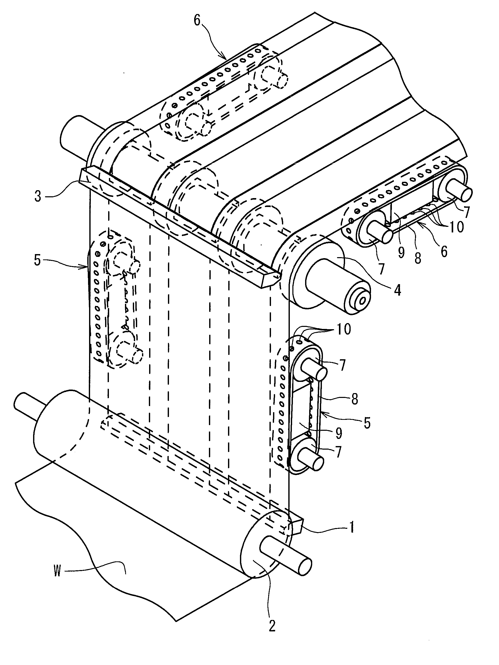
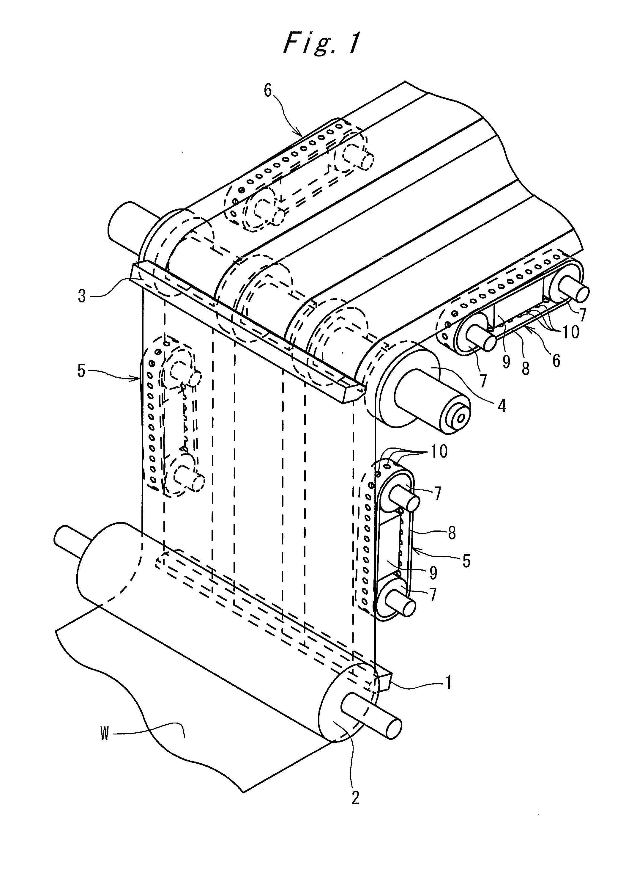
[0026]Hereinafter, embodiments of the present invention will be described referring to the attached drawings. FIG. 1 shows a construction of a portion relating coating in a double side coating device as the present invention. The double coating device of this embodiment has a first coating head (coating die) 1 that applies coating material in a form of three lines at even intervals on a first surface (back side) of a web material W, a back up roller 2 that supports a second surface of the web material W in a position opposite to the first coating head 1, a second coating head (coating die) 3 that applies coating material in a form of three lines on a second surface (front surface) so that the three lines corresponds to the coating material applied to the first surface in opposite side, and a suction roller 4 that supports the first surface of the web material W in a position opposite to the second coating head 3.

[0027]This double side coating devise further has pairs of vacuum conve...

second embodiment

[0036]Next, FIGS. 6 and 7 show a suction roller 18 according to a double side coating device as the present invention. This suction roller 18 consists of an outer tube 19 and an inner tube 20. The outer tube 19 has annularly projecting supporting portions with suction holes 21 opening radially on its circumference to suck the uncoated portions of the web material W, and static pressure pad portions 24 provided between the supporting portions 22 with a number of small holes 23 opening over all outer face.

[0037]In the inner tube 22, two flow channels extending parallel in the axial direction are formed. One flow channel is a suction header channel 25 to be connected to unshown vacuum source, and the other is a pressure header channel 26 to be connected to unshown compressed air source. The inner tube 20 is formed with connecting grooves 27, 28 separated from each other in range of 90 degree in a position respectively opposing to the supporting portions and static pressure pad portions...


PUM


Abstract

It is provided a double side coating device which can maintain a thickness of a coated film in constant. The double side coating device has a back up roller supporting a web material (W), a first coating head that is placed opposite to the back up roller and that applies a coating material onto a first surface of the web material (W), a suction roller (4) that is provided with a plurality of supporting portions which projects annularly so as to contact with a uncoated portion of the first surface of the web material (W) and on circumference of which suction holes (14) are opened to suck atmosphere, and a second coating head (3) that is placed opposite to the suction roller (4) and that coats second surface of the web material (W) with a coating material.

Description

FIELD OF THE INVENTION[0001]The present invention relates to a double side coating device for applying coating material to both surfaces of a web material.DESCRIPTION OF THE RELATED ART[0002]In case that both surface of a web material should be coated, generally, the web material is coated on one surface with coating material and then dried to be rewound, with a one side coating device. The rewound web material is put again in the one side coating device to be applied with coating material on the other surface.[0003]With increasing of needs for electric vehicle and the like, density growth and price reduction of secondary battery are strongly required. In production of the secondary battery cell, a coating device that can apply active material to both surfaces of a metallic foil electrode is required.[0004]Generally, in a coating device applying coating material with a die head, a thickness of a coated film is maintained in constant by arranging the die head opposing to a web materi...

Claims


Application Information

Patent Timeline
Patent Type & Authority Applications(United States)
IPC IPC(8): B05C1/10
CPCB05C5/0254B05C9/04B05C5/0283Y02P70/50
Inventor NISHIO, TSUTOMUTOKUMOTO, TAKAO
Owner CHUGAI RO CO LTD
Why Eureka
Try Eureka