Machine and method for machining a part by micro-electrical discharge machining

a technology of micro-electric discharge and machining, which is applied in the direction of machining electric circuits, electrical-based machining electrodes, manufacturing tools, etc., can solve the problems of increasing productivity and restricting the operation of replacing the etching electrod

Inactive Publication Date: 2011-07-21
UNIV DE LYON 1 CLAUDE BERNARD +2
View PDF3 Cites 14 Cited by
  • Summary
  • Abstract
  • Description
  • Claims
  • Application Information

AI Technical Summary

Benefits of technology

[0029]In the above machine, the electrode is replaced less frequently because it is re-sharpened without any need to dismount it from the micro-electrical discharge machining machine. This feature therefore limits operations for replacing the etching electrode, thus increasing the productivity of this machine.
[0066]permitting the passage to the machining configuration only if the shape of the tip is within a predetermined template prevents the machining of a part with a defective electrode.

Problems solved by technology

This feature therefore limits operations for replacing the etching electrode, thus increasing the productivity of this machine.

Method used


Image

  • Machine and method for machining a part by micro-electrical discharge machining
  • Machine and method for machining a part by micro-electrical discharge machining
  • Machine and method for machining a part by micro-electrical discharge machining

Examples


Embodiment Construction

[0073]In these figures, the same references are used to designate the same elements.

[0074]Here below in this description, the characteristics and functions well known to those skilled in the art are not described in detail.

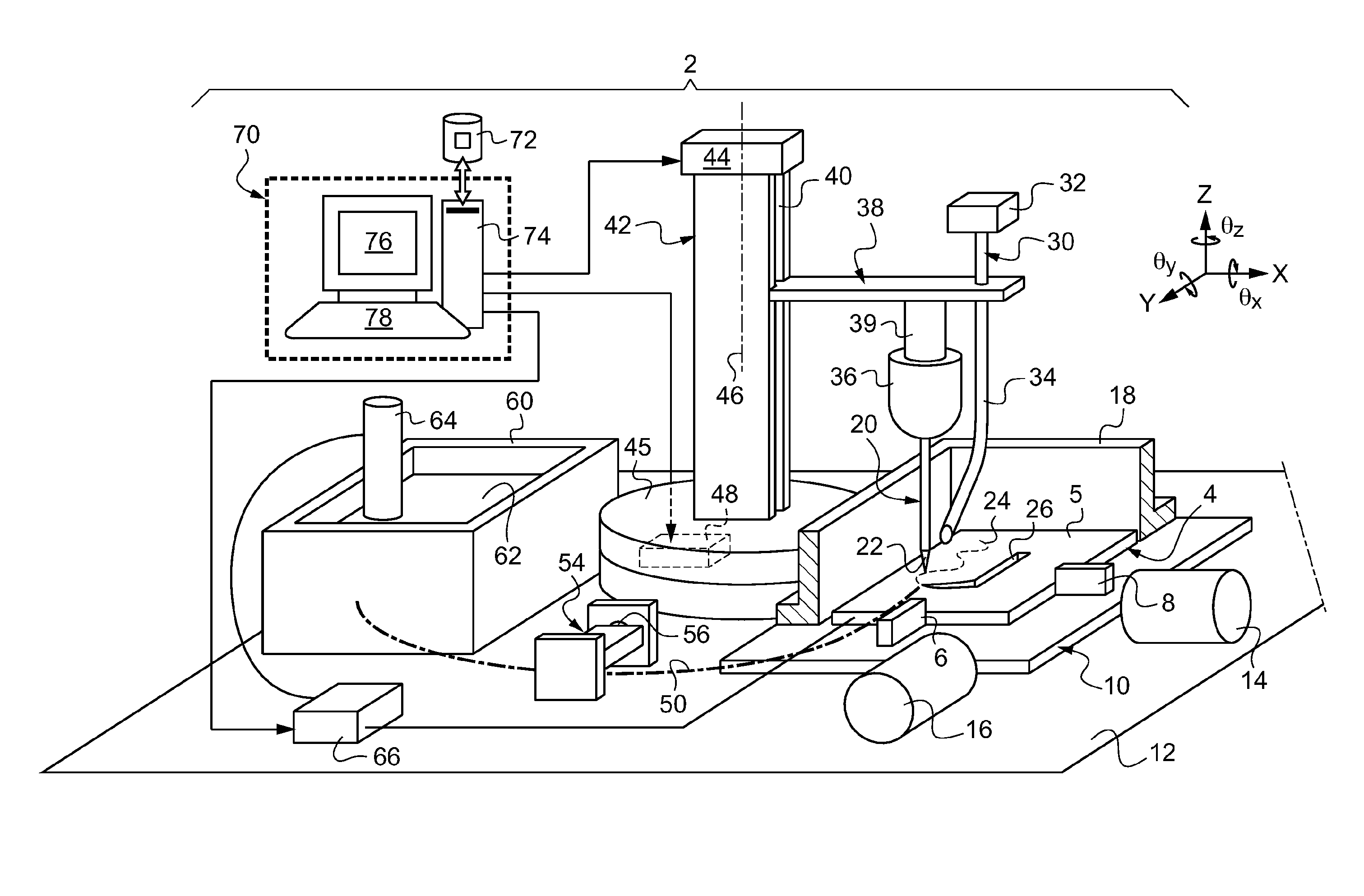
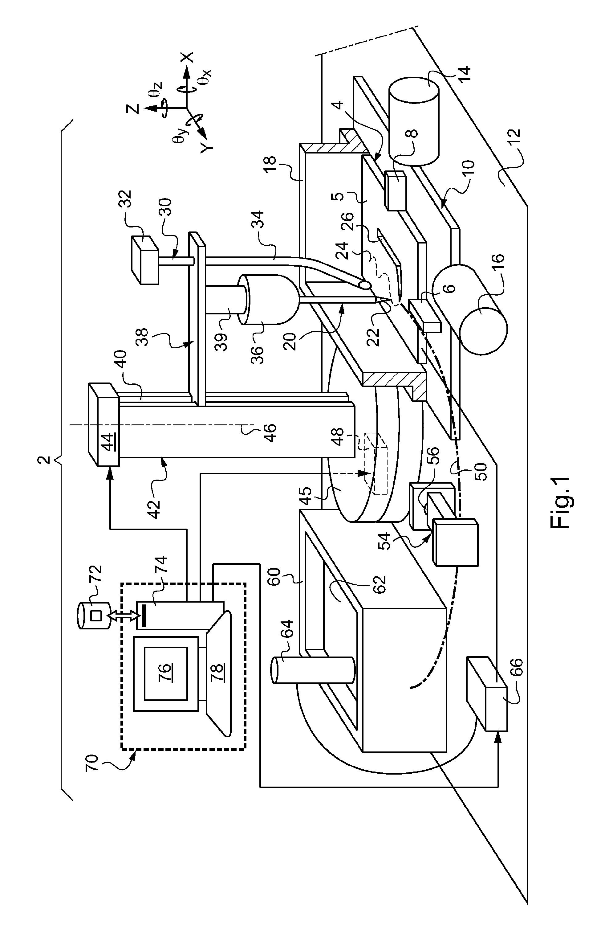
[0075]FIG. 1 shows a machine 2 for the micro-electrical discharge machining of a part 4. This machine 2 is configurable. It can pass from a machining configuration to a sharpening configuration and vice versa. In the machining configuration, the machine can be used to machine the part 4. In the sharpening configuration, the machine 2 can be used to sharpen an etching electrode. In this embodiment, to pass from the machining configuration to the sharpening configuration, an etching electrode can be transported from a machining station to a sharpening station. In FIG. 1, the machine is shown in its machining configuration.

[0076]Here, the part 4 is a parallelepiped substrate made out of a semi-conductive or conductive material. For example, the semi-conductive materi...


PUM

PropertyMeasurementUnit
cross-widthaaaaaaaaaa
diametersaaaaaaaaaa
diameteraaaaaaaaaa

Abstract

The invention relates to a machine for machining a part by micro-electrical discharge machining, said machine comprising a mechanism (44, 45, 46, 48) for modifying the configuration of the machine so as to alternatively and reversibly switch from a machining configuration to a sharpening configuration in which the tip of a same etching electrode (20) and another electrode (64) are dipped in an electrolyte bath in order to sharpen the tip of the etching electrode by electrochemnical corrosion.

Description

FIELD OF THE INVENTION[0001]The invention pertains to a machine and a method for machining a part by micro-electrical discharge machining.BACKGROUND OF THE INVENTION[0002]Electrical discharge machining is generally also known by the acronym EDM. Its miniaturization (micro-EDM or μEDM) has different variants depending on the shape of the etching electrode (which here below will also be called here a micro-electrode). These variants are the following:[0003]Die-sinking micro-electrical discharge machining in which a microelectrode with a shape complementary to the shape to be machined is sunken into the part.[0004]Wire micro-electrical discharge machining with a conductive wire circulating or driven by an alternating motion.[0005]The drilling of holes by micro-electrical discharge machining with a tip electrode or a tube electrode.[0006]Milling micro-electrical discharge machining better known as milling EDM.[0007]Milling micro-electrical discharge machining does not necessarily imply ...

Claims


Application Information

Patent Timeline
Patent Type & Authority Applications(United States)
IPC IPC(8): B23H3/04B23H9/00
CPCB23H3/04B23H5/02B23H7/065B81C2201/0146B23H9/00B23H9/08B23H7/08B81C1/00
Inventor CABRERA, MICHEL
Owner UNIV DE LYON 1 CLAUDE BERNARD
Why Eureka
Try Eureka