Glass roll, device for producing glass roll, and process for producing glass roll

a technology of glass roll and glass plate, which is applied in the direction of glass tempering apparatus, light beam reproducing, instruments, etc., can solve the problems of resin film inferior in barrier property, deterioration of light-emitting body, and inability to replace glass plate, etc., to achieve high strength and reliably prevent such a situation

Active Publication Date: 2011-07-21
NIPPON ELECTRIC GLASS CO LTD
View PDF17 Cites 68 Cited by
  • Summary
  • Abstract
  • Description
  • Claims
  • Application Information

AI Technical Summary

Benefits of technology

[0036]According to the present invention described above, the each end surface in the width direction of the glass film is constituted by the cut surface cut by the laser cutting, and hence has a smooth cross-section surface with high strength free from small flaws and the like which may cause breakage. Therefore, it is possible to provide a glass roll capable of reliably preventing such a situation that the glass film may break from the each end surface in the width direction of the glass film as an origin of breakage due to impact of external collision and concentration of stress.

Problems solved by technology

However, there is a problem in that the resin film is inferior to the glass plate in gas barrier property.
In a case of the OLED display, a light-emitting body to be used is deteriorated due to contact with gas, such as oxygen or water vapor, and hence the resin film inferior in barrier property cannot be used in place of the glass plate.
Further, for the same reason, also in a field other than the OLED display, the resin film cannot be used in place of the glass plate in many cases.
However, when the glass plate is thinned into a film, i.e., a so-called glass film, breakage is more liable to occur.
Consequently, a package form used for transportation or the like becomes a major issue.
However, when the above-mentioned package forms are adopted to the glass film, the following problems arise.
That is, when adopting the former package form, there is a problem in that it is extremely difficult to maintain a posture in the propped state due to flexibility of the glass film.
Further, even if the glass film can be propped, there is a problem in that the glass film easily breaks due to its extreme bending or concentration of stress applied on a very fragile lower end portion of the glass film.
In contrast, when adopting the latter package form, load of all glass films situated on an upper side is applied to glass films situated on a lower side, and hence there is a problem in that the glass films situated on the lower side easily break.
However, in this package form, the glass films need to be placed so that the glass plates are placed in a straddling manner on a plurality of support members arranged in parallel in a horizontal direction at intervals, and hence the package form is not suitable for packaging the glass film having flexibility.
That is, the glass film has flexibility, and hence it is difficult to place the glass film in a straddling manner on the support members, and placing of the glass film forces a complicated operation.
Further, even if the glass film can be placed, all load of the glass film is supported only by contact portions with the support members, and hence stress is concentrated on the supported portions so that the glass film may break.
Further, the glass film is bent downward due to its self-weight, and hence the glass film situated on the upper side may be held in direct contact with the glass film situated on the lower side, to thereby cause breakage.

Method used


Image

  • Glass roll, device for producing glass roll, and process for producing glass roll
  • Glass roll, device for producing glass roll, and process for producing glass roll
  • Glass roll, device for producing glass roll, and process for producing glass roll

Examples


Embodiment Construction

[0054]In the following, a glass roll and a glass roll manufacturing method according to a preferred embodiment of the present invention are described with reference to the drawings.

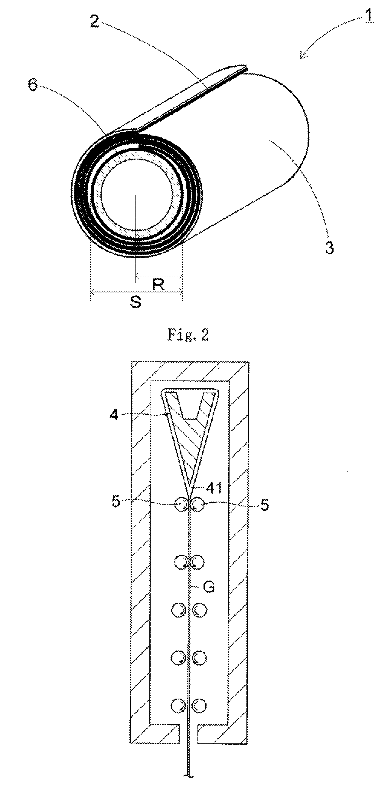
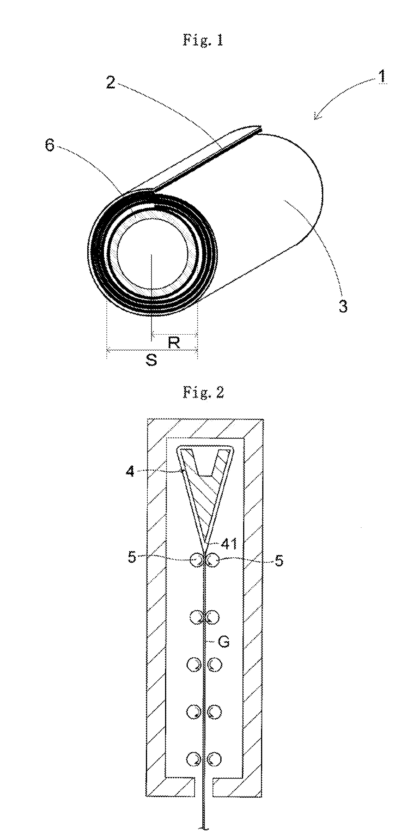
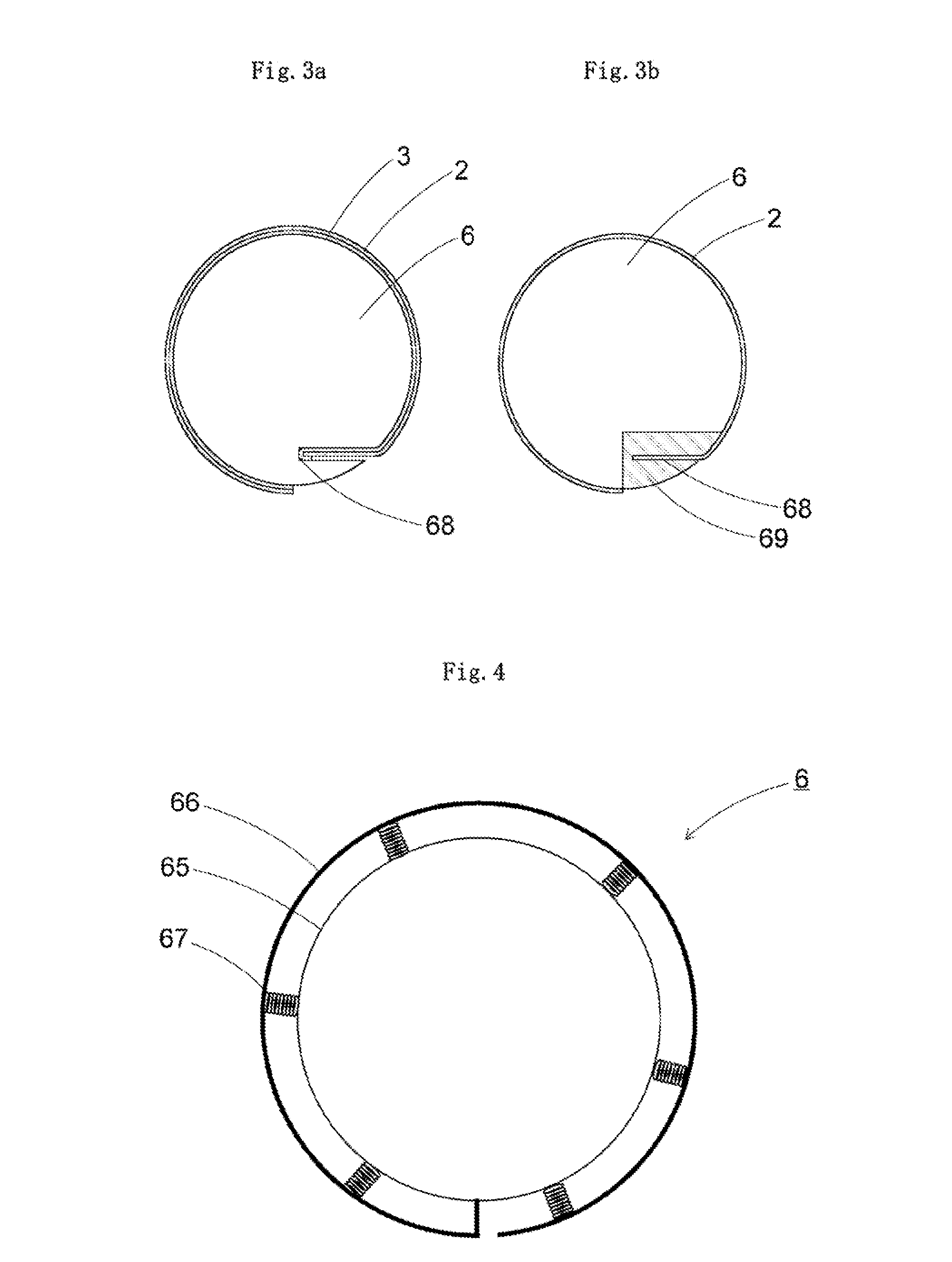
[0055]FIG. 1 is a perspective view of the glass roll according to the present invention. FIG. 2 is an explanatory diagram of a manufacturing device for a glass film. FIG. 3 are views each illustrating a mode of providing a holding portion to a roll core, in which Part (a) is a view illustrating a mode of holding the glass film and a protective sheet, and Part (b) is a view illustrating a mode of holding only the glass film. FIG. 4 is a view illustrating a mode in which an outer cylinder of the roll core expands and contracts. FIG. 5 is an explanatory diagram of a glass roll manufacturing device according to the present invention. FIG. 6 is an explanatory diagram illustrating a method of applying heat of laser irradiation onto the glass film and splitting the glass film using thermal stress caused by the h...


PUM

PropertyMeasurementUnit
thicknessaaaaaaaaaa
thicknessaaaaaaaaaa
thicknessaaaaaaaaaa

Abstract

To provide a glass roll capable of reliably preventing a glass film from breaking from an end surface of the glass film as an origin of breakage, a glass roll (1) is formed by winding a glass film (2) into a roll while superposing the glass film (2) on a protective sheet (3), the glass film (2) being formed by an overflow downdraw method to have a thickness of 1 μm or more and 200 μm or less, and to have each end surface in a width direction to form a cut surface cut by laser splitting.

Description

TECHNICAL FIELD[0001]The present invention relates to an improved technology for a package form for a glass film which is used as a glass substrate for a flat panel display and a solar cell, and used as cover glass or the like for an organic light-emitting diode (OLED) lighting.BACKGROUND ART[0002]In view of space saving, in recent years, there is widely used a flat panel display, such as a liquid crystal display, a plasma display, an organic light-emitting diode (OLED) display, or a field emission display, in place of a cathode ray tube (CRT) display that has been conventionally and widely used. Such a flat panel display is required to be further thinned. In particular, the OLED display is required to allow easy carrying by being folded or wound, and to allow use not only on a flat surface but also on a curved surface. Further, it is not limited to only the display to be required to allow the use not only on a flat surface but also on a curved surface. For example it is also requir...

Claims


Application Information

Patent Timeline
Patent Type & Authority Applications(United States)
IPC IPC(8): C03B33/02B32B17/00C03B17/06
CPCB65H18/28Y10T428/26B32B17/064B65H2801/61B32B17/10C03B23/033B65D85/672C03B33/0222C03B15/02B65D57/004
Inventor TOMAMOTO, MASAHIROETA, MICHIHARUODA, HIDETAKATAKAYA, TATSUYAYAMAZAKI, YASUOTAKIMOTO, HIROSHIISHIBASHI, SHINICHITAKAGI, KEIJINAGATA, DAISUKENAKAMURA, TAKAHIDESAKURABAYASHI, TORUFUJIWARA, KATSUTOSHINODA, MITSUHARUOGISO, YASUHIKOFUJII, TAKAHIDE
Owner NIPPON ELECTRIC GLASS CO LTD
Why Eureka
Try Eureka