Water management system
- Summary
- Abstract
- Description
- Claims
- Application Information
AI Technical Summary
Benefits of technology
Problems solved by technology
Method used
Image

Examples
example 1
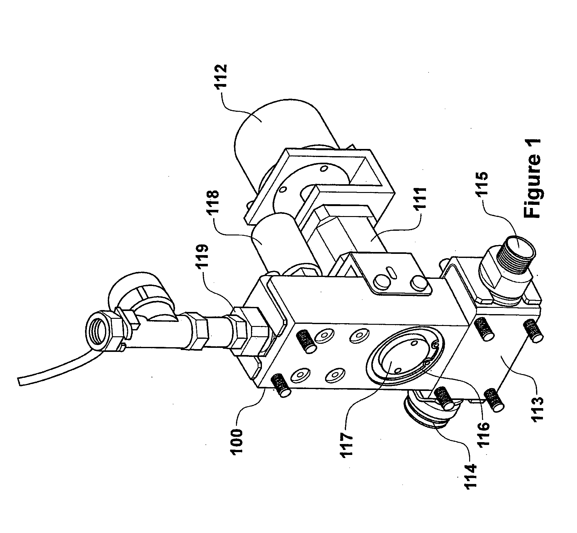
[0102]The prototype valve body for use with the water management system of this invention can best be understood from the cross sectional views of FIGS. 3 and 5. Looking at FIG. 1 it is apparent that there is a valve body 100 connected to an electric motor 111 and a shaft encoder 112, such that the electric motor causes a crank pin 131 to rotate. The crank pin passes through the centre of the valve body at right angles to the main rectangular axis of the valve body.
[0103]At the bottom of the valve body there is the intake manifold 113 with inlet connector 114 at the left hand side of FIG. 1, and a connector 115 at the right-hand side of FIG. 1. These connectors enable a number of valve bodies to be connected together to a common inlet pipe.
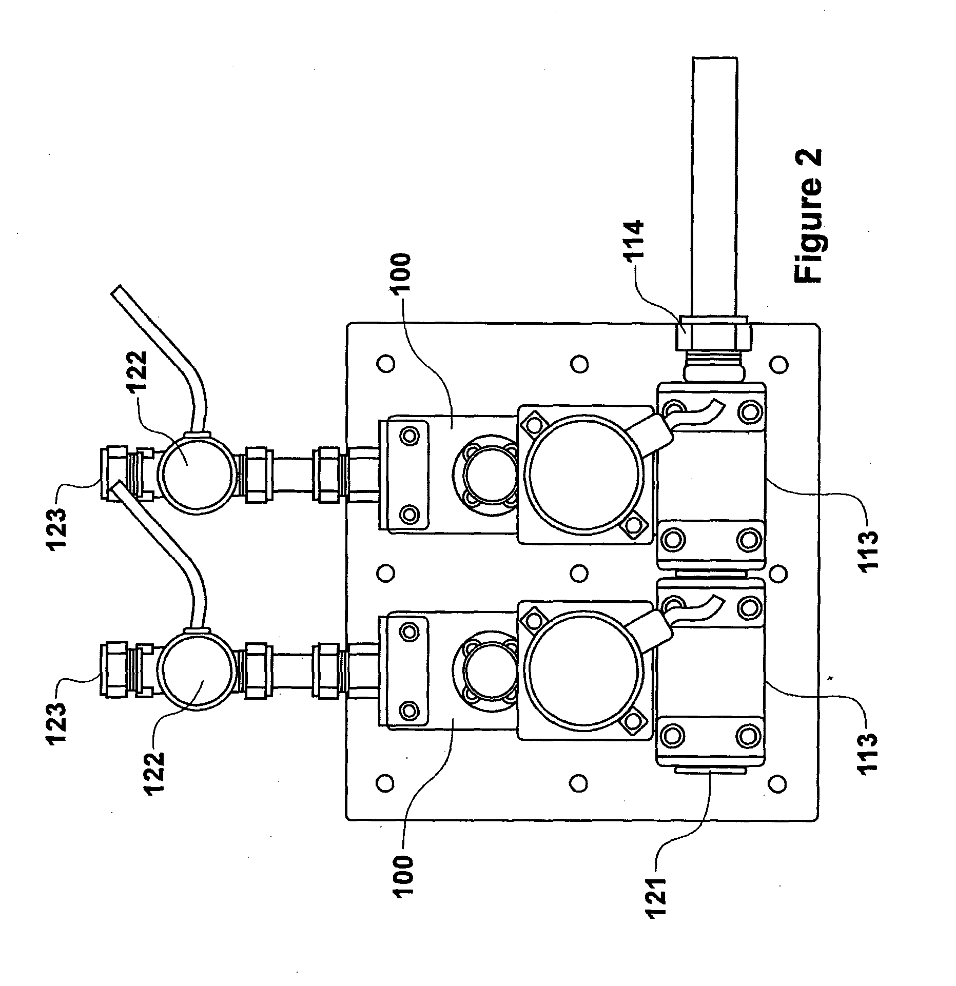
[0104]FIG. 2 shows a pair of valve bodies connected together with the inlet connector 114 on the right-hand side of FIG. 2, and an end unit blanking plug 121 positioned at the left hand side of the leftmost valve body.
[0105]In FIG. 2 water flows f...
example 2
[0128]In this example, the prototype valve of Example 1 has been redesigned to make a more compact production valve by reducing the size of the pressure transducer, and replacing the large and somewhat cumbersome stepper motor of the prototype with its absolute encoder, with a much smaller conventional DC motor which drives through a reduction gear box and has its own integral shaft encoder mounted on the rear shaft of the motor. All of the valve body and the internal components have been machined from an engineering plastic, but the valve and its components can be injection moulded.
[0129]In addition we have reduced the size of the assembly by incorporating a paddle wheel flow meter inside the body of the valve (as shown in FIG. 14) and have mounted, a control printed circuit board (PCB) on the front of the valve as well so that the whole unit is now self contained. This PCB may contain the controller which controls the position of the electric motor and hence the opening and closin...
example 3
[0136]This is a prototype installation intended to mimic the plumbing installation of a standard dwelling where there are a number of outlets to taps, showers, toilet systems, appliances such as dishwashers and washing machines, garden taps, and the like.
[0137]For example this standard dwelling might be a 3 bedroom home.
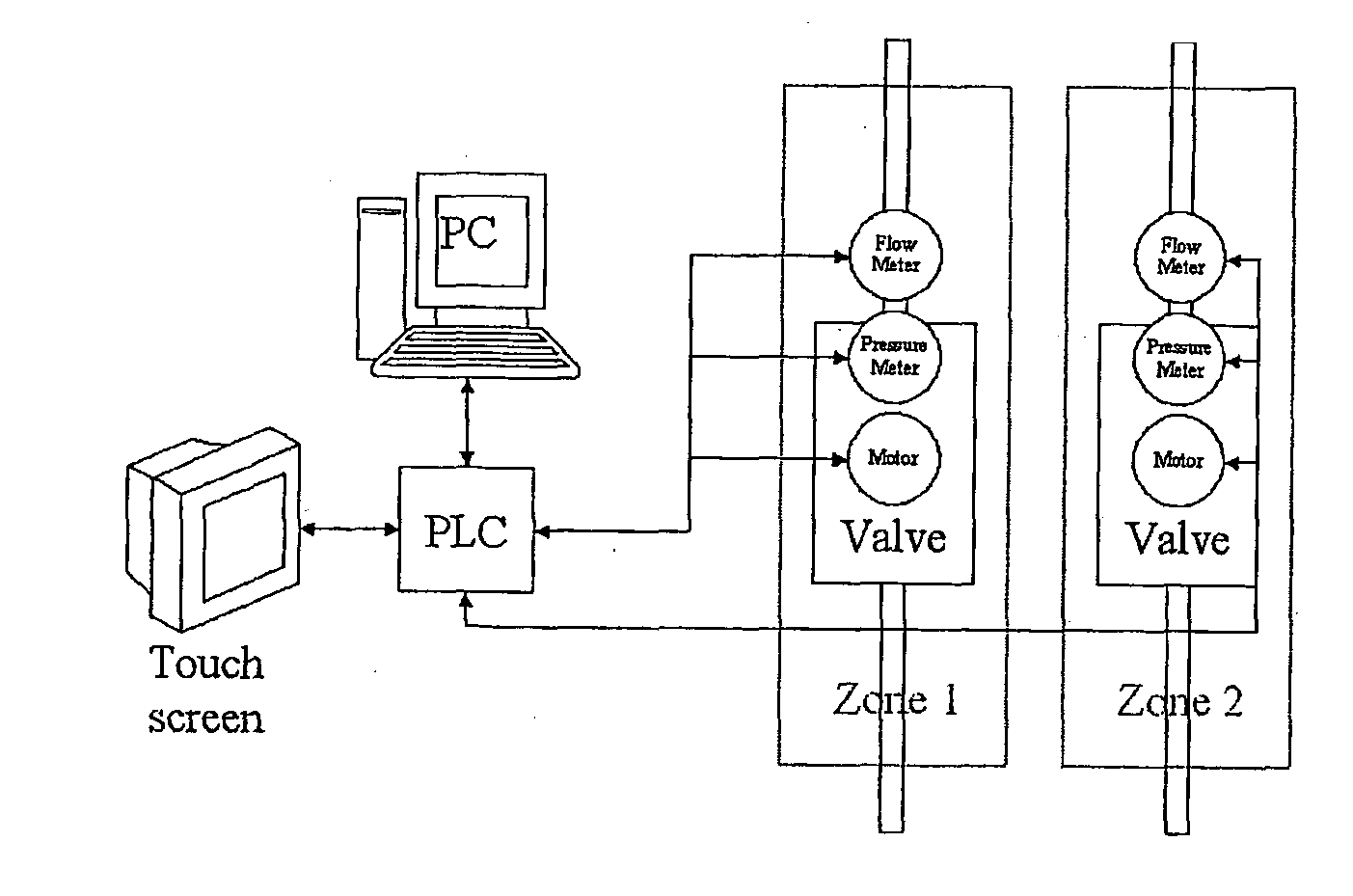
[0138]In this installation the dwelling is divided into two zones, each zone has a zone feed pipe designated zone 1 feed pipe 1111 and zone 2 feed pipe 1112 and each one of those feed pipes is connected to a branch leading to an outlet. For convenience each outlet is designated first by the zone and then by the outlet number. For example in zone 1 outlet 11113a may be a cold water tap in a hand basin, whilst zone 1 outlet 21113b might be the supply to a toilet cistern, whilst zone 2 outlet 1117 might be a connection to a dishwasher. Each of the zones is controlled by a respective valve unit 1115 shown in FIGS. 1 and FIG. 2.
[0139]Each of these valve units 1115 is an e...
PUM
 Abstract
Description
Claims
Application Information
 - R&D
- Intellectual Property
- Life Sciences
- Materials
- Tech Scout
- Unparalleled Data Quality
- Higher Quality Content
- 60% Fewer Hallucinations
Browse by: Latest US Patents, China's latest patents, Technical Efficacy Thesaurus, Application Domain, Technology Topic, Popular Technical Reports.
© 2025 PatSnap. All rights reserved.Legal|Privacy policy|Modern Slavery Act Transparency Statement|Sitemap|About US| Contact US: help@patsnap.com