Speed Change System for Work Vehicle

a technology for work vehicles and speed changes, which is applied in the direction of gearing, fluid couplings, instruments, etc., can solve the problems of affecting the smooth operation of the work vehicle in a large load situation, the vehicle speed is unlikely to be stabilized during the low-speed traveling, and the engine stall due to overload is likely to be generated, so as to achieve excellent performance and reduce the effect of operability

Active Publication Date: 2011-07-21
KUBOTA LTD
View PDF3 Cites 64 Cited by
  • Summary
  • Abstract
  • Description
  • Claims
  • Application Information

AI Technical Summary

Benefits of technology

[0011]Therefore, it is desirable to provide a speed change system for a...

Problems solved by technology

As a result, it becomes difficult for the work vehicle to smoothly travel in a large load situation, such as hill-climbing traveling and a working state in which a working device is connected.
In addition, in a low-speed region in which the change gear ratio of the hydrostatic continuously variable transmission device is made large by operating the speed change operation tool to the low-speed side, an angle on a low-speed side exhibiting low hydraulic pressure transmission efficiency is more frequently used as the swash plate angle of the variable capacity pump, and thus a vehicle speed is unlikely to be stabilized during the low-speed traveling.
When the work vehicle is started in such a setting condition, a large load due to the small change gear ratio will be applied to the engine from a stage with a low engine rotational speed, and therefore, engine stall due to overload is likely to be generated.
Especially in a case where the work vehicle is started in a situation where a load is large, such as in ascending a slope or in a working state with the working device connected, there is a notable tendency that engine stall occurs, and the accelerator operation should be further carefully performed.
However, it has be...

Method used


Image

  • Speed Change System for Work Vehicle
  • Speed Change System for Work Vehicle
  • Speed Change System for Work Vehicle

Examples


Embodiment Construction

[0046]Hereinbelow, as one example of embodiment to carry out the present invention, a case in which a speed change system of a work vehicle according to the present invention is applied to a tractor as one example of the work vehicle will be described with reference to the drawings.

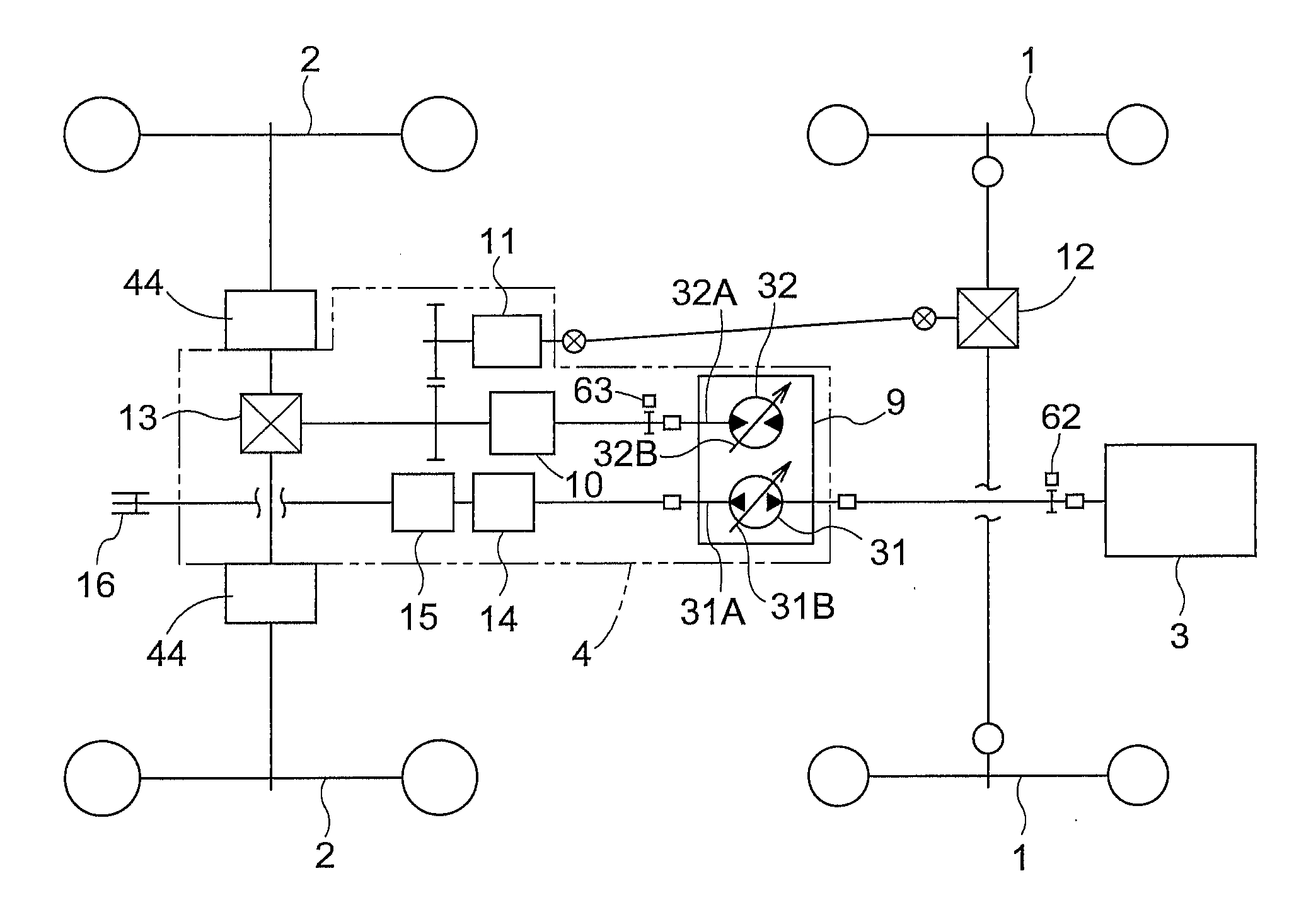
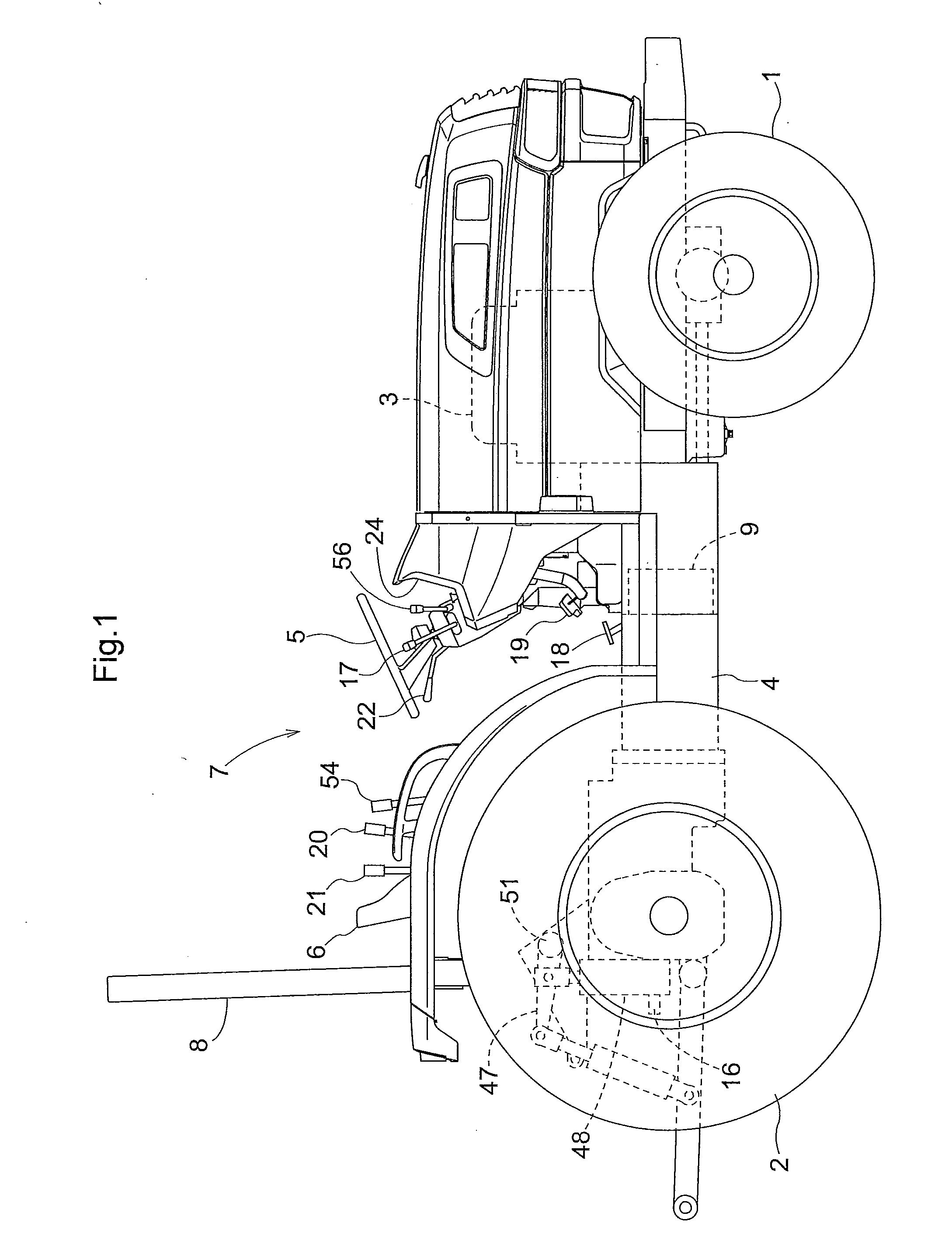
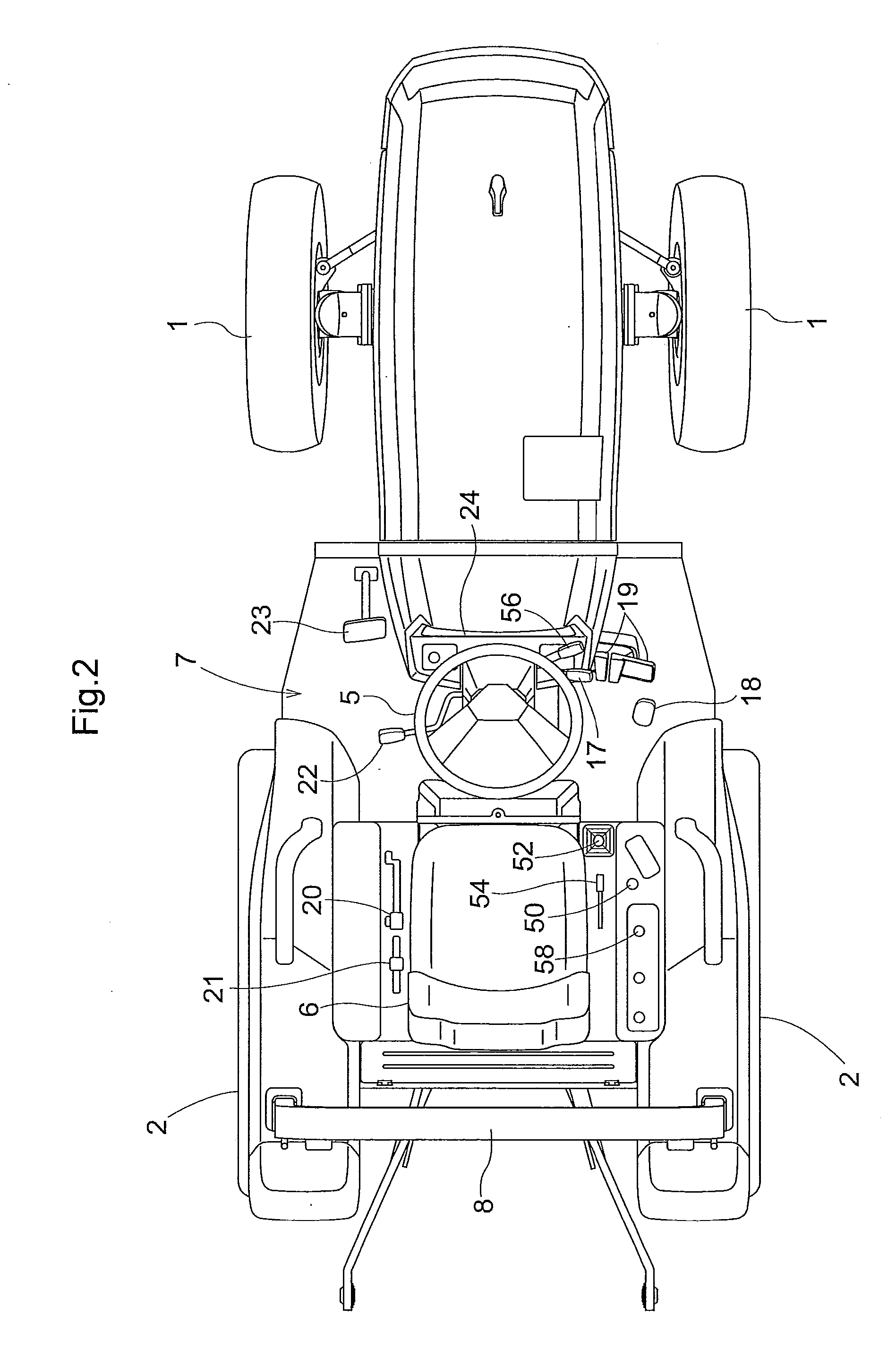
[0047]As shown in FIGS. 1 and 2, the tractor is configured as four-wheel-drive type including a pair of right and left front wheels 1 which are steerable and drivable, and a pair of right and left rear wheels 2 which are drivable and to which braking is independently applicable. A front portion side of the tractor has an engine 3 mounted thereon, and to a rear portion of the engine 3, a transmission case (hereinafter, referred to as “T / M case”) 4, also serving as a body frame, is connected. In a rear portion side of the tractor, a steering wheel 5 for front wheel steering and a driver's seat 6 are disposed to form a boarding operation part 7, and a gate-shaped protection frame 8 is vertically arranged.

[00...


PUM


Abstract

A speed change system for work vehicle having a continuously variable transmission device selects a first change gear ratio which is set larger than a smallest change gear ratio, when an engine rotational speed is a first set rotational speed which is set equal or close to an idling rotational speed of an engine; retains the change gear ratio of the continuously variable transmission device at the smallest change gear ratio, when the engine rotational speed is equal to or above a second set rotational speed set on a high-speed side relative to the first set rotational speed; and makes the change gear ratio of the continuously variable transmission device larger between the first change gear ratio and the smallest change gear ratio, as the engine rotational speed at that moment becomes lower, when the engine rotational speed is between the first and second set rotational speeds.

Description

BACKGROUND OF THE INVENTION[0001]1. Field of the Invention[0002]The present invention relates to a speed change system for a work vehicle including: a pump swash plate operation mechanism configured to operate a swash plate of a variable capacity pump for continuously variable transmission device; a motor swash plate operation mechanism configured to operate a swash plate of a variable capacity motor for the continuously variable transmission device; a swash plate angle control unit for controlling the pump swash plate operation mechanism and the motor swash plate operation mechanism; and an operation position detector configured to detect an operation position of a speed change operation tool. A swash plate angle of the variable capacity pump is non-stepwise changed, and a swash plate angle of the variable capacity motor is stepwise changed.[0003]2. Description of the Related Art[0004]For such a speed change system for a work vehicle, Japanese Unexamined Patent Application Publicat...

Claims


Application Information

Patent Timeline
IPC IPC(8): B60W10/10F16H39/00B60W30/18
CPCB60W2510/0638F16H61/421F16H61/431F16H61/47F16H2061/6615Y10T477/688F16H2059/363F16H2059/366B60W10/101B60W10/196Y10T477/621F02D31/00
Inventor UMEMOTO, SUSUMUMUKAI, HISAOICHIKAWA, NOBUSHIGEINAMORI, TAKUYAMATSUZAKI, YUSHI
Owner KUBOTA LTD
Why Eureka
Try Eureka