Control device of automatic engine stop and start

Active Publication Date: 2011-07-21
DENSO CORP
View PDF12 Cites 50 Cited by
  • Summary
  • Abstract
  • Description
  • Claims
  • Application Information

AI Technical Summary

Benefits of technology

[0049]Because the control device according to the fourth aspect of the present invention drives the pre-set control means to prohibit the execution of the pre-set control immediately after the gear meshing failure occurs under the pre-set control while the rotation speed of the internal combustion engine is dropping due to the automatic engine stop, during which it is difficult for the control device to detect the engine rotation spee

Problems solved by technology

However, when the rotation speed of the pinion gear is different from the rotation speed of the ring gear, that is, when there is no synchronization of rotation speed between these gears, there is a possibility of generating large gear meshing noise and damage between these gears because the pinion gear cannot be smoothly meshed with the ring gear due to such a large difference of rotation speed between these gears.
However, because the pre-gear meshing control starts the cranking after the rotation speed of the internal combustion engine is almost stopped when the engine restart request is issued while the rotation speed of the internal combustion engine is dropping due to the automatic engine stop, a delay time period counted from the time when such the engine restart request is issued to the time when the internal combustion engine is actually restarted.
This delay time period gives uncomfortable drive to the driver of the vehicle.
However, there is a possibility for the control device to cause a failure of the engine restart even if performing the engine self-restart control.
For example, there is a high possibility for the control device to cause a failure of the engine restart when the dropping rate of the rotation speed of the internal combustion engine is high.
In this case, because the pinion gear is pushed to the ring gear side while the rotation speed of the ring gear is greatly larger than that of the pinion gear (that is, under the condition where the rotation speed of the ring gear is not synchronized with that of the pinion gear), it becomes difficult to smoothly perform the gear meshing operation between the pinion gear and the ring gear.
This generates large gear meshing noise and abrasion of the ring gear and the pinion gear, and causes large impact to the starter.
In this case, the control device executes the same control again, and this has a high probability of causing the same engine restart failure.
By the way, there is a possibility of causing the engine restart failure due to an engine trouble such as a difficulty of performing the desired engine combustion even if the control device executes the engine self-restart control.
Further, there is a possibility of causing the gear meshing failure by pushing the pinion gear to the ring gear when no gear synchronization of rotation speed between the pinion gear and the ring gear is obtained even if the control device executes the pre-gear synchronizing control.
Further, there is a possibility of causing the engine restart failure on the basis of the gear meshing failure due to aging deterioration of the pi

Method used


Image

  • Control device of automatic engine stop and start
  • Control device of automatic engine stop and start
  • Control device of automatic engine stop and start

Examples


first embodiment

[0069]A description will be given of the engine control device according to a first embodiment of the present invention with reference to FIG. 1 to FIG. 7.

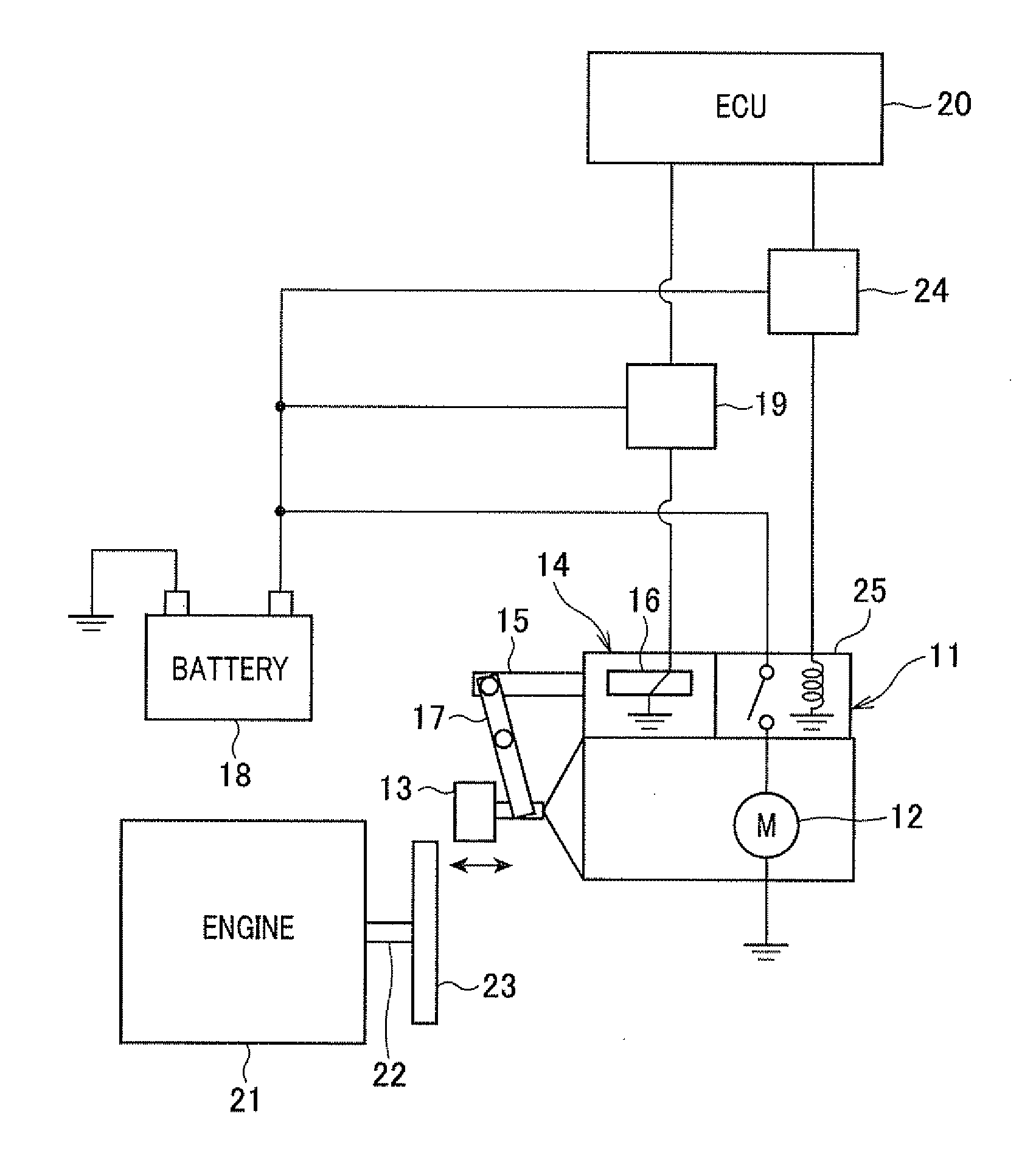
[0070]FIG. 1 is a view showing a schematic configuration of the engine start control system having the control device for executing the automatic engine stop and start routine according to first to sixth embodiments of the present invention.

[0071]A starter 11 has a mechanism for pushing a pinion gear 13 to a ring gear 23 in order to mesh these gears and start the cranking when the internal combustion engine 21 is started to work. The starter 11 has a mechanism for pushing the pinion gear 13 to the ring gear 23 in order to perform the gear engagement between these gears when the internal combustion engine 21 is started and restarted. The ring gear 23 is fixed to the crank shaft 22 of the internal combustion engine 21. The starter 11 is comprised of a starter motor 12, the pinion gear 13, and an electromagnetic actuator 14. The pini...

second embodiment

[0168]A description will be given of the engine restart control executed by the ECU 20 in the control device according to a second embodiment of the present invention with reference to FIG. 8.

[0169]FIG. 8 is a flow chart showing an engine restart control routine executed by the ECU 20 in the control device according to the second embodiment when a failure of the engine self-restart control occurs.

[0170]In the engine restart control according to the first embodiment previously described, the ECU 20 prohibits or halts the execution of the pre-gear synchronizing control during the predetermined time period Tb which is counted from the failure detection time t40. The ECU 20 executes the pre-gear meshing control at the time t50 which is elapsed from the failure detection time t40 by the predetermined time period Tb.

[0171]On the other hand, in the second embodiment, the ECU 20 prohibits the execution of the pre-gear synchronizing control until the rotation speed Ne of the internal combust...

third embodiment

[0187]A description will be given of the engine restart control executed by the ECU 20 in the control device according to a third embodiment of the present invention with reference to FIG. 9.

[0188]In the first and second embodiments previously described, the ECU 20 executes the engine self-restart control, the pre-gear synchronizing control, and the pre-gear meshing control, respectively, according to the first rotation speed range, the second rotation speed range, and the third rotation speed range.

[0189]On the other hand, the ECU 20 according to the third embodiment does not execute the pre-gear synchronizing control which corresponds to step S105 shown in FIG. 5. In the third embodiment, the ECU 20 executes one of the engine self-restart control and the pre-gear meshing control according to the first rotation speed range and the third rotation speed range.

[0190]FIG. 9 is a flow chart showing the engine restart control routine executed by the ECU 20 in the control device according...


PUM


Abstract

In a control device, an engine self-restart means tries the engine restart when an engine restart request is issued while the engine rotation speed is within a first rotation speed range. A pre-gear synchronizing control means executes gear rotation speed synchronization between pinion and ring gears, and then retries the engine restart when the engine restart request is issued while the engine rotation-speed is within a second rotation speed range. A pre-gear meshing control means executes gear-meshing between the pinion and ring gears and then retries the engine restart when the engine restart request is issued while the engine rotation speed is within a third rotation speed range. On detecting the engine-restart failure of the engine self-restart control, the control device prohibits the execution of pre-gear synchronizing control until a predetermined time counted form the failure detection time is elapsed, and executes the pre-gear meshing control after the predetermined time period is elapsed.

Description

CROSS-REFERENCE TO RELATED APPLICATION[0001]This application is related to and claims priority from Japanese Patent Applications No. 2010-009678 filed on Jan. 20, 2010, No. 2010-009679 filed on Jan. 20, 2010, and No. 2010-265587 filed on Nov. 29, 2010, the contents of which are hereby incorporated by reference.BACKGROUND OF THE INVENTION[0002]1. Field of the Invention[0003]The present invention relates to control devices for controlling automatic engine stop and start. The control device is capable of automatically stopping the internal combustion engine of a vehicle on receiving an automatic engine stop request, and automatically restarting the internal combustion engine on receiving an engine restart request.[0004]2. Description of the Related Art[0005]There is a recent trend for vehicles to be equipped with an automatic engine control system capable of automatically stopping and starting the internal combustion engine of a vehicle in order to improve fuel consumption and reduce e...

Claims


Application Information

Patent Timeline
IPC IPC(8): F02D41/30F02D45/00
CPCF02N11/0844F02N11/0855Y02T10/48F02N2200/022F02N11/101Y02T10/40
Inventor OKUMOTO, KAZUSHIGEFUJITA, TATSUYANOTANI, HIDEYA
Owner DENSO CORP
Why Eureka
Try Eureka