Light guide device

a technology of light guide and guide rod, which is applied in the direction of lasers, beacon systems, cosmonautic components, etc., can solve the problems of not always providing as much control over the range of output angles, and achieve the effect of reducing the amount of input light required, and improving optical coupling efficiency

Inactive Publication Date: 2011-07-28
ITI SCOTLAND
View PDF11 Cites 85 Cited by
  • Summary
  • Abstract
  • Description
  • Claims
  • Application Information

AI Technical Summary

Benefits of technology

[0019]There are numerous advantages associated with the various aspects of the present invention including: improved optical coupling efficiency into a desired range of output angles; less steep topology to the microlens surface; minimal stray light that may create unwante

Problems solved by technology

However, such a system does not always provide as much control over

Method used


Image

  • Light guide device
  • Light guide device
  • Light guide device

Examples


example 1

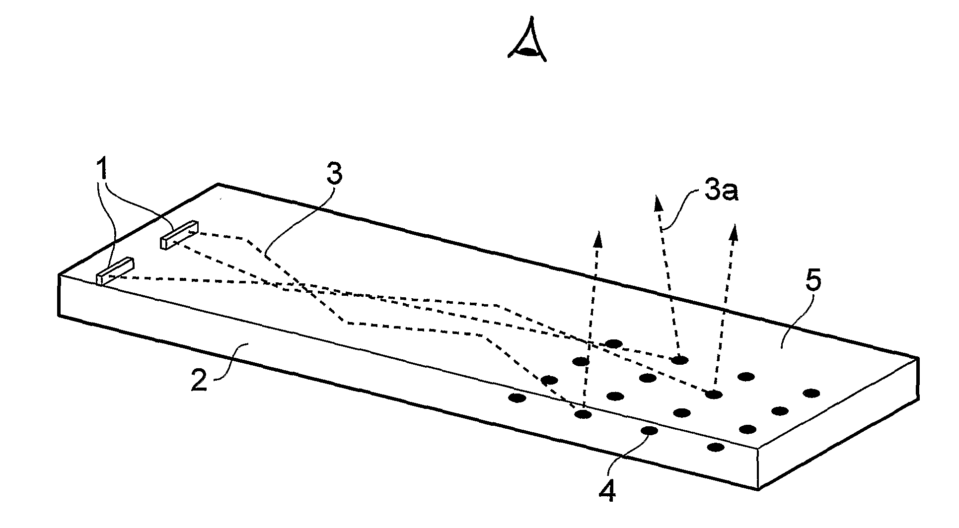
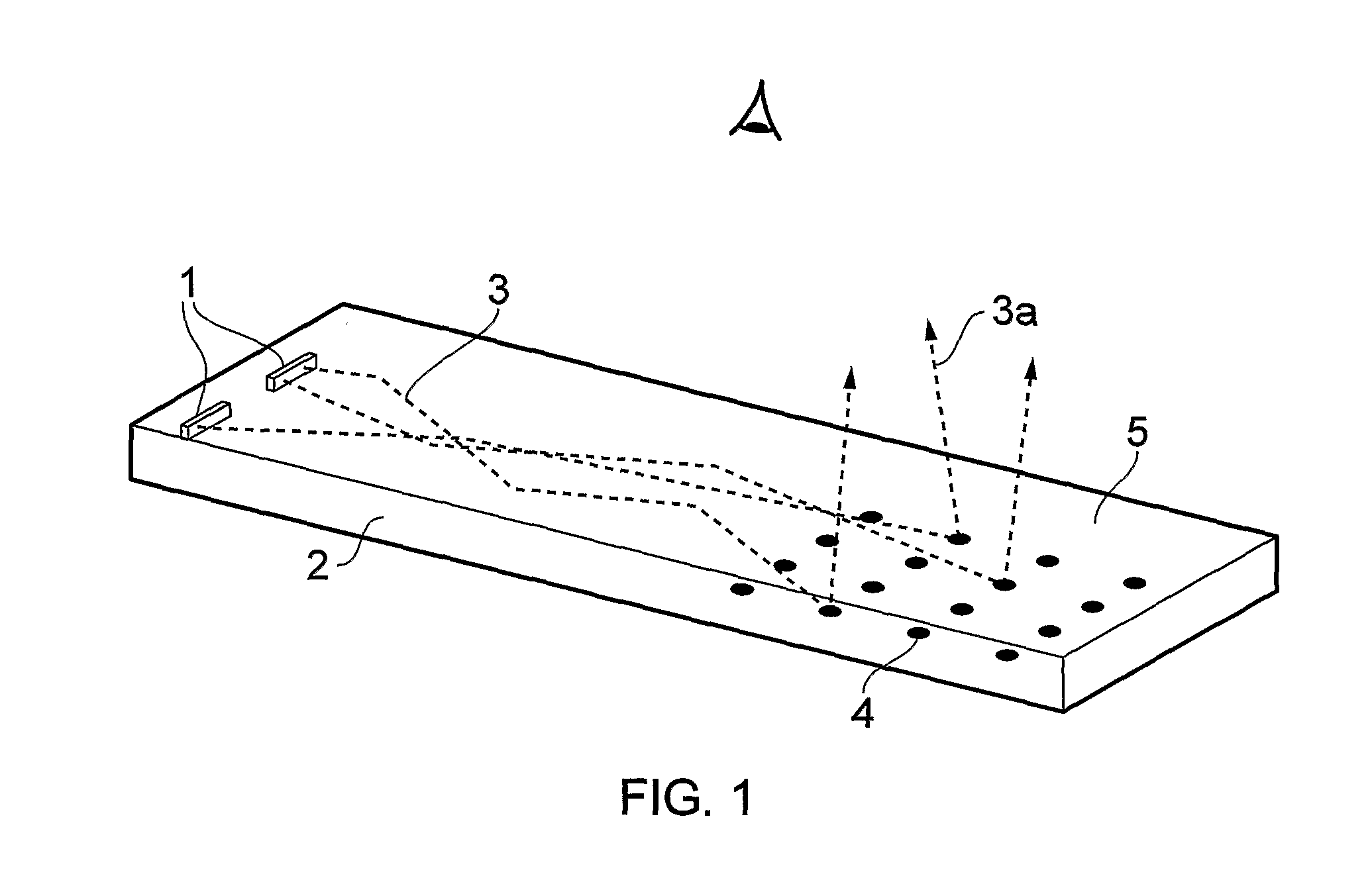
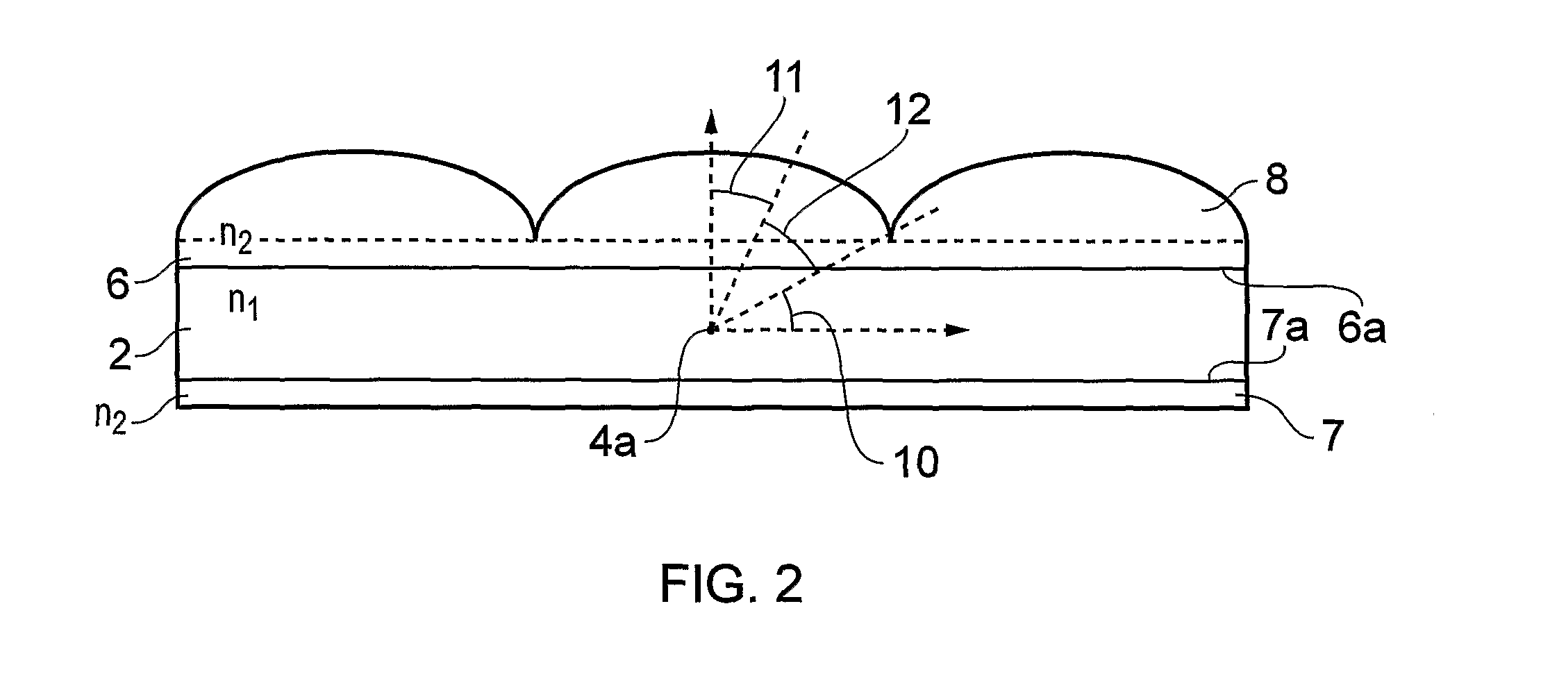
[0044]A regular dot pattern (scattering features) was printed onto a PMMA sheet (core light guide layer) using screen printing ink impregnated with TiO2 particles. Cladding layers made from FEP were laminated onto either side of the core using a pressure sensitive adhesive. Along the exposed main surface of one of the cladding layers, an aluminium coated FEP layer was attached (reflector layer), also using pressure sensitive adhesive. On the exposed main surface of the other cladding layer, an array of individual injection-moulded, hemispherical polystyrene microlenses was attached directly above and in line with the scattering features using a uv-curing adhesive. The device was illuminated from the side.

[0045]A calculation was performed using Zemax ray tracing software on two systems (a) n1=n3=1.5 and n2=1.3 and (b, comparative) n2=n3=1.3 and n1=1.5. The difference in output distributions is shown in FIG. 5. The distribution of light for the arrangement according to the present inv...


PUM


Abstract

Light guide devices comprising an intermediate layer of low refractive index between higher refractive index elements are described. The light guide devices are suitable for use in backlights.

Description

FIELD OF THE INVENTION[0001]This invention relates to a light guide device. The light guide device is suitable for use in a range of applications, particularly in connection with the backlighting of displays, for example, liquid crystal displays.BACKGROUND OF THE INVENTION[0002]The angular distribution of light coming from a backlight is important in determining both the efficiency and the viewing angle of the display that it illuminates.[0003]Edge lit backlights guide light from the edge of the light guide to points all over the area of the output of the light guide. Light confined within the guide and propagating within the guiding angle of the guide, may be scattered by scattering structures, such as point like defects, on the surface of the guiding layer. Powdered TiO2 is an example of a suitable scattering material. An illustration of such a system is shown in FIG. 1.[0004]In FIG. 1, LEDs (1) are arranged at the edge of a transparent polymer core light guide layer (2). Light (3...

Claims


Application Information

Patent Timeline
IPC IPC(8): F21V7/22F21V8/00H01L33/00H01S3/00
CPCG02B6/0036G02B6/0043G02B6/0073G02B6/0068G02B6/0065G02B6/0033G09F13/18G09F2013/1863
Inventor TOMLINSON, ANDREW MICHAEL
Owner ITI SCOTLAND
Why Eureka
Try Eureka