

Device And Method For Particle Therapy Verification
- Summary
- Abstract
- Description
- Claims
- Application Information
AI Technical Summary
Benefits of technology
Problems solved by technology
Method used
Image

Examples
embodiment 1
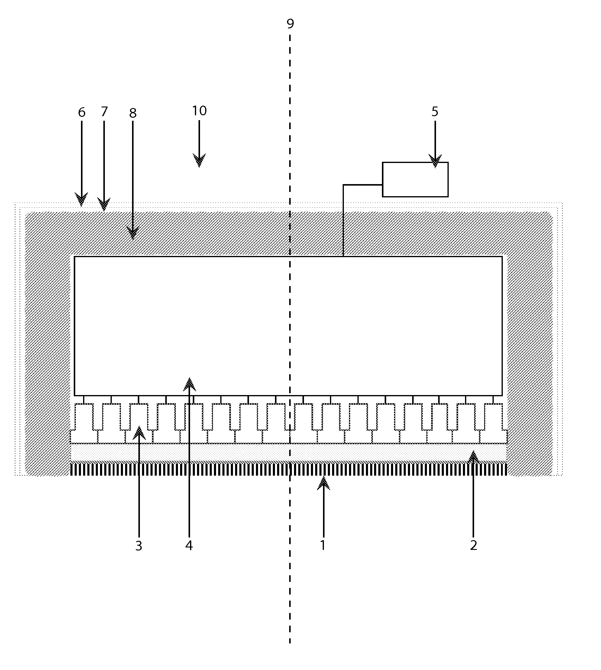
[0123]In one preferred embodiment an Anger camera (10) is used to detect the prompt gammas emitted in a direction essentially at 90° with respect to the beam direction.
[0124]The camera (10) is installed such that its optical axis (9) is perpendicular to the beam direction, in order to detect prompt gammas emitted from the object at 90°.
[0125]The same principle can be used by putting the camera in a different geometry with respect to the beam direction and measuring prompt gammas at different angles.
[0126]The Anger camera (10) is equipped with appropriate shielding against neutrons, X-ray and unwanted gamma-rays.
[0127]As depicted in FIG. 4 the camera (10) comprises a plurality of collimators (1) that are made of high atomic number material such as Pb or W, on top of which at least one scintillating crystal (2) is laid.
[0128]The at least one scintillating crystal is optically coupled to at least one photomultiplier tube (3), each of them being connected to appropriate readout electron...
embodiment 2
[0143]In another preferred embodiment a pinhole camera is used to detect the prompt gammas emitted from the irradiated body or object.
[0144]The camera is installed such that is optical axis (30) is perpendicular to the beam direction, in order to detect prompt gammas emitted from the object.
[0145]The pinhole gamma camera is equipped with shielding against neutrons, X-ray and unwanted gamma-rays.
[0146]As depicted in FIG. 5 the pinhole camera (20) is equipped with a pinhole collimator (21) made in a high atomic number material such as Pb or W.
[0147]An advantage of using a pin-hole camera when compared with an Anger camera is that a pin-hole camera can be better shielded for background irradiation.
[0148]A problem with the Anger camera is the fact that to obtain a high resolution when measuring the distribution of prompt gammas, the distance between the collimators is small (few mm, e.g. 2 or 3 mm) and hence the effective shielding is reduced.
[0149]Preferably, the section following any ...
PUM
 Abstract
Description
Claims
Application Information