Fuel cell and fuel cell stack

a fuel cell and stack technology, applied in the field of fuel cells, can solve the problems of easy damage or cracking of electrolyte electrode assemblies, inability to efficiently perform power generation of the entire fuel cell, and inability to prevent damage or cracking of the electrolyte electrode assembly, so as to prevent damage or cracking, improve heat efficiency, and suppress the radiation of heat generated

Active Publication Date: 2011-08-04
HONDA MOTOR CO LTD
View PDF3 Cites 4 Cited by
  • Summary
  • Abstract
  • Description
  • Claims
  • Application Information

AI Technical Summary

Benefits of technology

[0013]The present invention has been made to solve the problem of this type, and an object of the present invention is to provide a fuel cell and a fuel cell stack which make it possible to optimize distribution of an oxygen-containing gas supplied to cathodes and

Problems solved by technology

Further, in Japanese Laid-Open Patent Publication No. 2004-235060, since each cell forming plate 1a comprises one electrolyte electrode assembly, if any power generation failure occurs in one of the power generation cells, the failure causes malfunction in power generation of the entire fuel cell.
Therefore, power generation cannot be performed efficiently.
Therefore, the electrolyte electrode assembly tends to be damaged or cracked easily.
Further, it is not possible to suppress radiation of heat generated in the power generation, and heat efficiency is lowered.
By the excessive load applied to the electrolyte electrode assembly, the electrolyte electrode assembly may

Method used


Image

  • Fuel cell and fuel cell stack
  • Fuel cell and fuel cell stack
  • Fuel cell and fuel cell stack

Examples


first embodiment

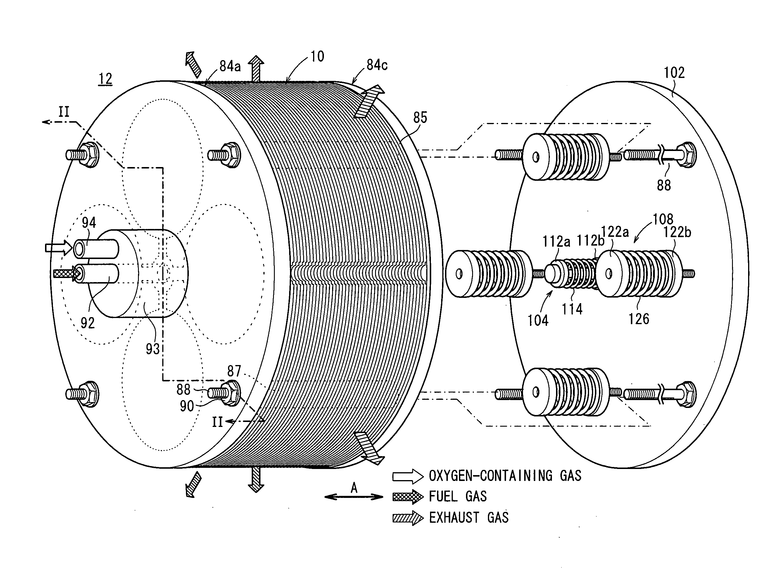
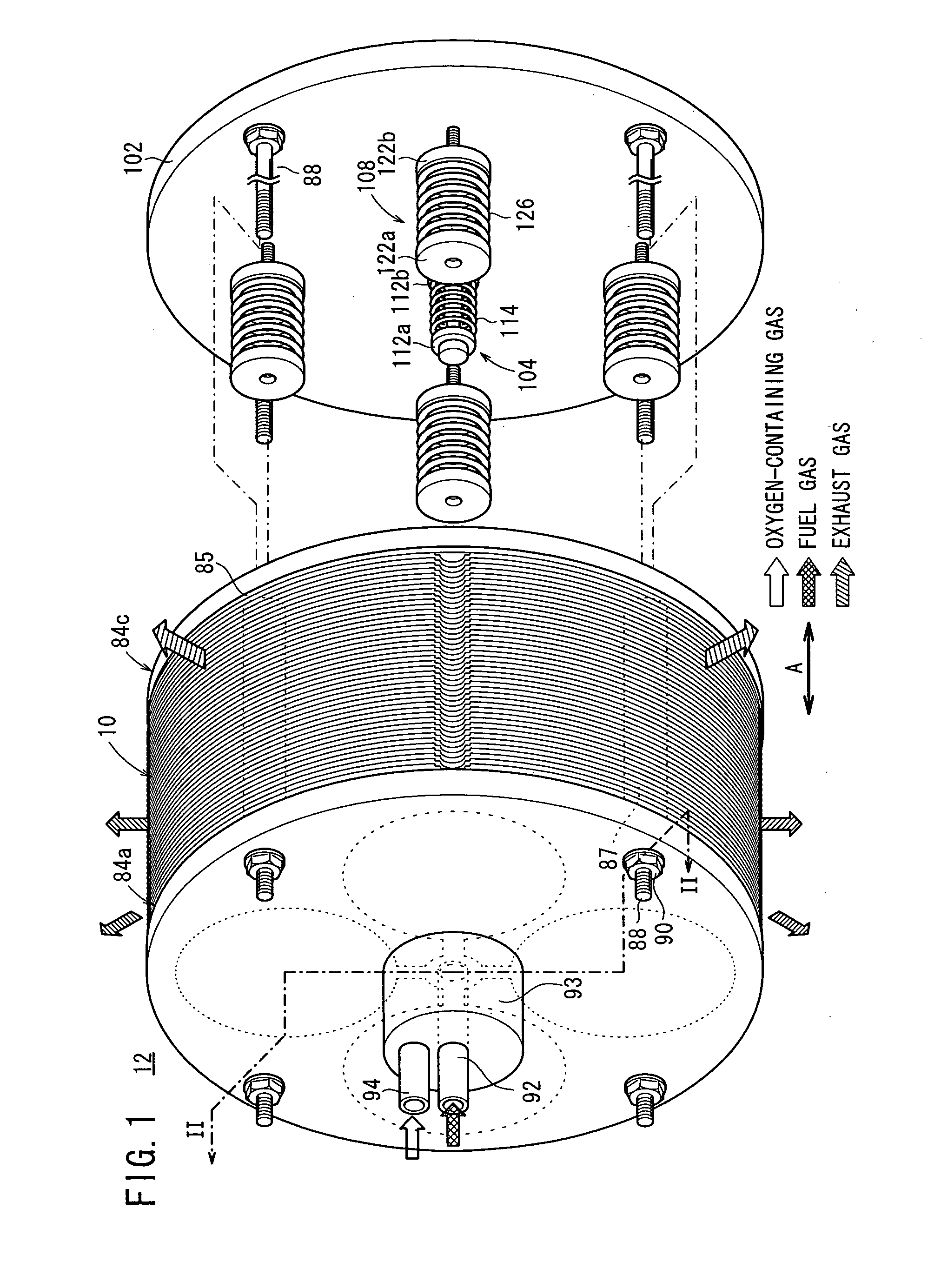
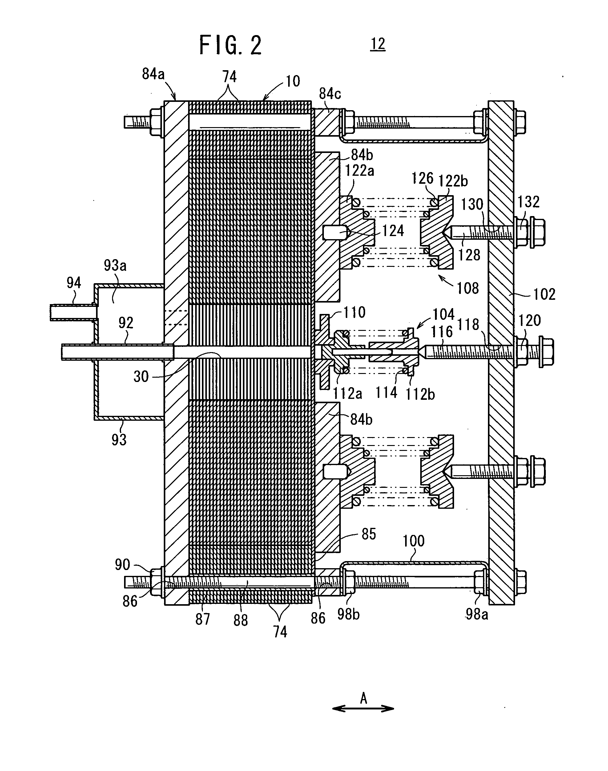
[0045]FIG. 1 is a perspective view schematically showing a fuel cell stack 12 formed by stacking fuel cells 10 according to the present invention in a direction indicated by an arrow A. FIG. 2 is a cross sectional view showing the fuel cell stack 12 taken along a line II-II in FIG. 1.

[0046]The fuel cell 10 is a solid oxide fuel cell (SOFC) used in various applications, including stationary and mobile applications. For example, the fuel cell 10 is mounted on a vehicle. As shown in FIGS. 3 and 4, the fuel cell 10 includes electrolyte electrode assemblies (MEAs) 26. Each of the electrolyte electrode assemblies 26 includes a cathode 22, an anode 24, and an electrolyte (electrolyte plate) 20 interposed between the cathode 22 and the anode 24. For example, the electrolyte 20 is made of ion-conductive solid oxide such as stabilized zirconia. The electrolyte electrode assembly 26 has a circular disk shape. A barrier layer (not shown) is provided at least at the outer circumferential edge of...

second embodiment

[0096]In the second embodiment, the flow rectifier member 136 is made of heat insulating material. Therefore, radiation of heat generated in the electrolyte electrode assemblies 26 to the outside of the sandwiching sections 36 is suppressed. Thus, it is possible to improve heat efficiency easily.

[0097]Further, the space L3 between the adjacent flow rectifier members 136 near the oxygen-containing gas inlet of the electrolyte electrode assembly 26 is smaller than the space L4 between the adjacent flow rectifier members 136 near the oxygen-containing gas outlet of the electrolyte electrode assembly 26. In the structure, the oxygen-containing gas flows smoothly on the electrolyte electrode assembly 26, and the pressure loss is reduced effectively.

[0098]In the second embodiment, the flow rectifier member 136 is made of heat insulating material. Alternatively, the flow rectifier member 136 may be made of electrically insulating material, and the flow rectifier member 74 may be made of he...

third embodiment

[0099]FIG. 10 is an exploded perspective view showing a fuel cell 140 according to the present invention.

[0100]The fuel cell 140 includes separators 28, and a mesh member (electrically conductive woven fabric such as metal mesh) 142 instead of the plate 50 is provided on the surface 36b of each of the sandwiching sections 36 of the separators 28 (see FIGS. 10 and 11). An oxygen-containing gas channel 54 is formed in the mesh member 142. A cutout 142a is formed in the mesh member 142 as a space for providing the second bridge 64 of the channel member 60.

[0101]In the third embodiment, the same advantages as in the case of the first and second embodiments are obtained. Though the mesh member 142 is used in the third embodiment, instead of the mesh member 142, for example, an electrically conductive felt member (electrically conductive non-woven fabric such as metal felt), foam metal, expanded metal, punching metal, or pressed embossed metal may be used.


PUM


Abstract

A fuel cell includes separators sandwiching electrolyte electrode assemblies. Each of the separators includes a fuel gas supply section, four first bridges extending radially outwardly from the fuel gas supply section, sandwiching sections connected to the first bridges, and flow rectifier members provided between adjacent sandwiching sections. A fuel gas supply passage extends through the center of the fuel gas supply section. Each of the sandwiching sections has a fuel gas channel and an oxygen-containing gas channel. The flow rectifier members rectify the flow of the oxygen-containing gas supplied from the oxygen-containing gas supply passage to the electrolyte electrode assemblies.

Description

TECHNICAL FIELD [0001]The present invention relates to a fuel cell formed by stacking electrolyte electrode assemblies between separators. Each of the electrolyte electrode assemblies includes an anode, a cathode, and an electrolyte interposed between the anode and the cathode. Further, the present invention relates to a fuel cell stack formed by stacking a plurality of the fuel cells.BACKGROUND ART [0002]Typically, a solid oxide fuel cell (SOFC) employs an electrolyte of ion-conductive solid oxide such as stabilized zirconia. The electrolyte is interposed between an anode and a cathode to form an electrolyte electrode assembly (MEA). The electrolyte electrode assembly is interposed between separators (bipolar plates). In use, generally, predetermined numbers of the electrolyte electrode assemblies and the separators are stacked together to form a fuel cell stack.[0003]In the fuel cell of this type, Japanese Laid-Open Patent Publication No. 2004-235060 discloses a fuel cell having a...

Claims


Application Information

Patent Timeline
IPC IPC(8): H01M8/24H01M8/10
CPCH01M8/0204Y02E60/525H01M8/0252H01M8/0263H01M8/0265H01M8/0267H01M8/04022H01M8/04074H01M8/04097H01M8/1206H01M8/243H01M8/248H01M8/249H01M2008/1293Y02E60/521H01M8/023H01M8/1231H01M8/2432H01M8/2457H01M8/2483Y02E60/50
Inventor SAITO, BUNICHIKIYOHIRO, YUKIHIKO
Owner HONDA MOTOR CO LTD
Why Eureka
Try Eureka