
System and method for well test design, interpretation and test objectives verification

a well and test design technology, applied in the field of well test design, interpretation and test objective verification, can solve the problems of not being able to properly decide about the test sequence in advance, the test may not be properly designed by the test designer, waste of rig and testing equipment time, etc., to achieve the effect of enhancing and adding value to well testing operations, reducing the number of development wells employed, and improving field performan

Inactive Publication Date: 2011-08-04
SCHLUMBERGER TECH CORP
View PDF9 Cites 55 Cited by
  • Summary
  • Abstract
  • Description
  • Claims
  • Application Information

AI Technical Summary

Benefits of technology

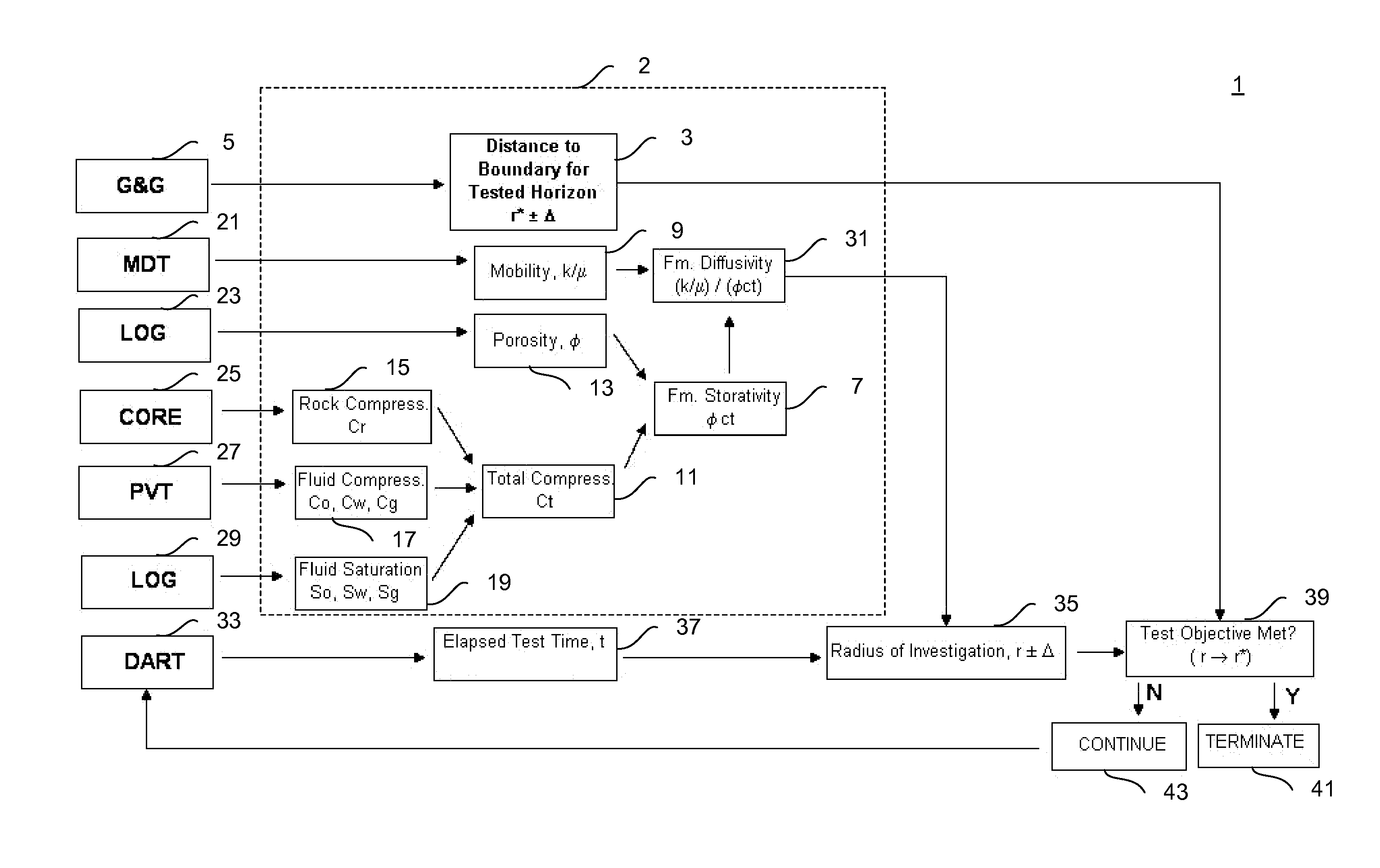
[0014]In addition, there is a need for a method and system that addresses discovered problems with existing systems and methods for well testing. The above and other needs and problems are addressed by an improved method and system, referred to as a Test Design and Interpretation Process (TDIP), for well test design and interpretation, that allow for the making of crucial decisions related to well production efficiency, operations, and safety, well workover, and reservoir management based on real-time measurements of well downhole and surface pressure, temperature, flow rate, and the like. Data is acquired from various tools, such as a multiphase flowmeter, e.g., an assignee's flowmeter, for measuring the flow rate and the oil, water and gas content of the well effluent continuously with downhole pressure measurements during reservoir testing. The data is interpreted real-time to enable production and reservoir engineers and managers to optimize well completion, perforation, lift, production, recovery, and the like. As each well represents a large investment in drilling and completion, the reservoir and well knowledge gained from dynamic testing data integrated by the TDIP, advantageously, can help to reduce the number of development wells employed, and provide for a better prediction of field performance, the ability to pinpoint future infill drilling opportunities, and the like.
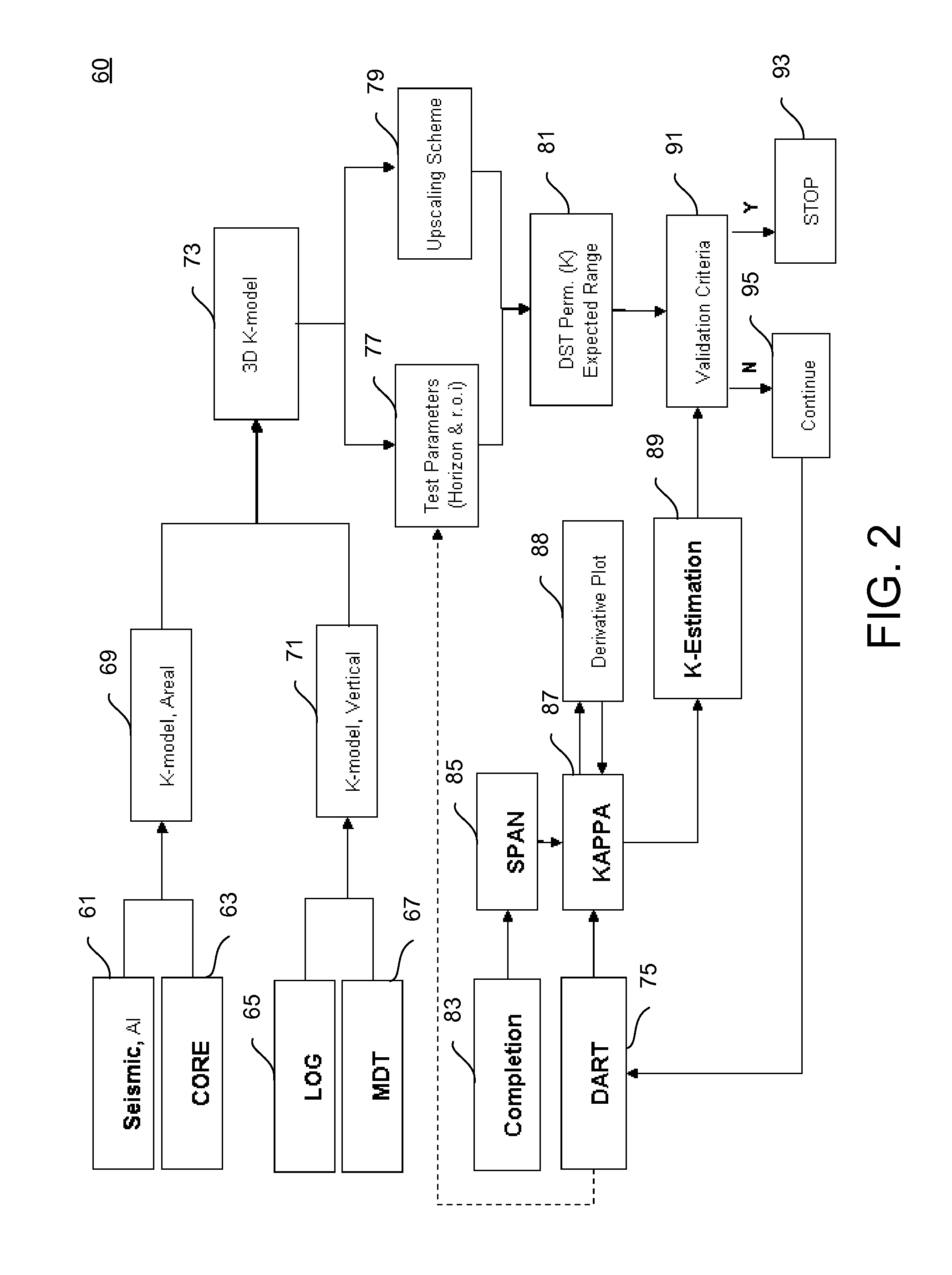
[0015]In an exemplary embodiment, the exemplary system and method can include the TDIP used in conjunction with a Testing Manager Platform and Real-Time data acquisition system (Testing Manager) to enable exploration and production companies and testing reservoir engineers to enhance and add value to well testing operations, test design, interpretation, and successful completion of a well test. Furthermore, the exemplary system and method help to reduce uncertainty in complex geological systems. The TDIP synthesizes the well test measurements, such as pressure, flow rate, temperature, and the like, with a geological model of the reservoir to model these measurements and anticipate the encounter of geological features, such as faults, fracture, and the like, while testing, in order not to terminate well testing prematurely. Advantageously, the novel well test design and interpretation system and method is continuous until the termination of the well test, wherein test data are received from various sensors via the acquisition system into the Testing Manager. The reservoir model is continuously updated as data comes in via the TDIP, wherein the Testing Manager provides real-time connections to design, interpretation, other toolboxes, and the like. The TDIP combined with the Testing Manager enables faster decision making with the potential to identify and reduce nonproductive testing time with and test design and interpretation. Advantageously, the TDIP can be used to update the model in real-time, enabling faster decision making and reducing testing time, and saving time and money.

Problems solved by technology

However, it is not always possible to properly decide about a test sequence in advance.
For example, expected and real reservoir parameters may differ considerably, and consequently, the test may not be properly designed by the test designer.
Therefore, the test program or individual segments of the test program (flowing and shut-in periods) may be too long or too short, which leads to waste of rig and testing equipment time or to the non-achievement of the defined test objectives, respectively.
In addition, crucial decisions relating to well production efficiency, operations, and safety, well workover, and reservoir management can require huge amounts of data, including measurements of well downhole and surface pressure, temperature, flow rate, etc.
However, conventional systems and methods suffer from not being able to efficiently process the acquired data, including downhole pressure measurement interpretation.

Method used


Image

  • System and method for well test design, interpretation and test objectives verification
  • System and method for well test design, interpretation and test objectives verification
  • System and method for well test design, interpretation and test objectives verification

Examples


Embodiment Construction

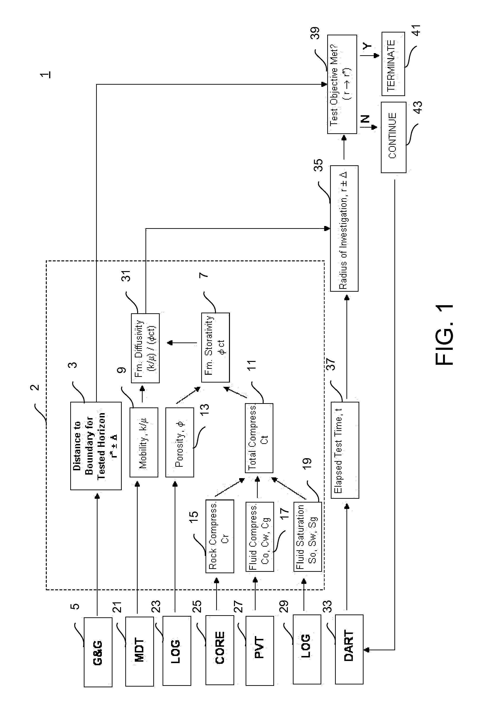
[0035]Referring now to the drawings, wherein like reference numerals may designate identical or corresponding parts throughout the several views, and more particularly to FIGS. 1-17 thereof, there are illustrated exemplary systems and methods for well test design, interpretation and test objectives verification.

[0036]The present disclosure includes recognition that in order to avoid loss of measurement data or waste of resources it has been proposed to assign the test engineer as the only responsible person for supervision of the well test procedure over the whole periods of test design, implementation, data acquisition and their quality control, and interpretation (see, e.g., Barnum and Vela “Testing Exploration Wells by Objectives,” paper SPE 13184 presented at the SPE Annual Technical Conference and Exhibition, Houston, Tex., USA, 16-19 Sep. 1984). Emphasis is placed on the importance of design execution of the test based on a detailed list of test objectives, wherein important t...


PUM


Abstract

A method and system for well test optimization provides test parameters and variation range therefor, independently from preliminarily reservoir and downhole fluid data; and repeatedly executes the test for each parameter to obtain real-time measured data, and interpreted data that is compared to the variation range for meeting a test objective. A method and system for well test design and interpretation, includes a testing manager having testing hardware / gauge metrology; a geological model; dynamic / static engineering data acquisition; and a reservoir model generator. A method and system for well test design and interpretation generates a test plan and an initial reservoir model and data from real / near-real-time, surface / downhole / manual data, aggregated data based on quality control / assurance, and optimization data based thereon and simulated downhole data; models / interprets the optimization data to meet test objectives for terminating / continuing the test plan; modifies the optimization; and / or generates reports from the modeling / interpretation when terminating the test plan.

Description

CROSS REFERENCE TO RELATED DOCUMENTS[0001]The present disclosure claims benefit of priority to U.S. Provisional Patent Application Ser. No. 61 / 035,233 of JALALI et al., entitled “METHOD TO VERIFY RESERVOIR INFORMATION CAPTURE DURING EXPLORATION WELL TEST OPERATIONS,” filed on Mar. 10, 2008, U.S. Provisional Patent Application Ser. No. 61 / 095,158 of KUCHUK et al., entitled “SYSTEM AND METHOD FOR WELL TEST DESIGN AND INTERPRETATION,” filed on Sep. 8, 2008, and U.S. Provisional Patent Application Ser. No. 61 / 104,050 of KUCHUK et al., entitled “SYSTEM AND METHOD FOR WELL TEST DESIGN AND INTERPRETATION,” filed on Oct. 9, 2008, the entire contents of all of which are hereby incorporated by reference herein.BACKGROUND[0002]1. Technical Field[0003]The present disclosure generally relates to methods and systems for well testing, including hydrocarbon formation evaluation techniques, and more particularly to a system and method for well test design, interpretation and test objectives verifica...

Claims


Application Information

Patent Timeline
IPC IPC(8): G06F19/00G01V3/18
CPCE21B49/087
Inventor JALALI, YOUNESAMINI, SHAHRAM
Owner SCHLUMBERGER TECH CORP
Learn More