Wireless Camera Coupling With Rotatable Coupling

Active Publication Date: 2011-08-11
KARL STORZ IMAGING INC
View PDF43 Cites 112 Cited by
  • Summary
  • Abstract
  • Description
  • Claims
  • Application Information

AI Technical Summary

Benefits of technology

[0026]Accordingly, some aspects of the present invention address the aforementioned problems by providing a method and system for contactless wireless inductive power transfer from the endoscopic camera head to an onboard light source in the endoscope, which may be positioned in a handle or in the shaft of an endoscope. This scheme allows for: 1) no lateral forces or moments from a laterally connected light guide; 2) unlimited relative rotation between camera head and endoscope shaft without light gui

Problems solved by technology

As such, the problems associated with inductive coupling such as radiated

Method used


Image

  • Wireless Camera Coupling With Rotatable Coupling
  • Wireless Camera Coupling With Rotatable Coupling
  • Wireless Camera Coupling With Rotatable Coupling

Examples


Embodiment Construction

[0050]Referring now to the drawings, wherein like reference numerals designate corresponding structure throughout the views.

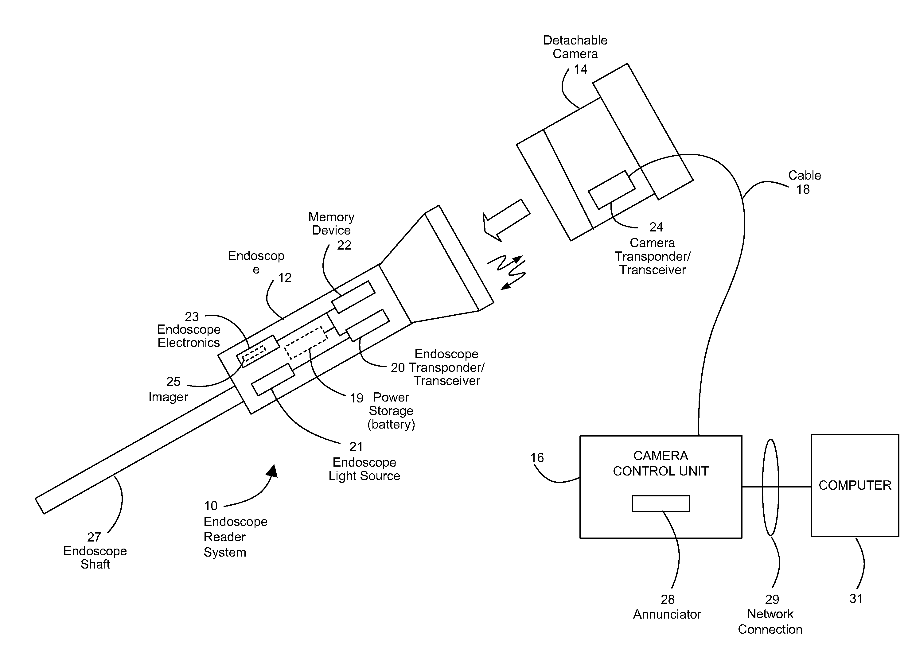
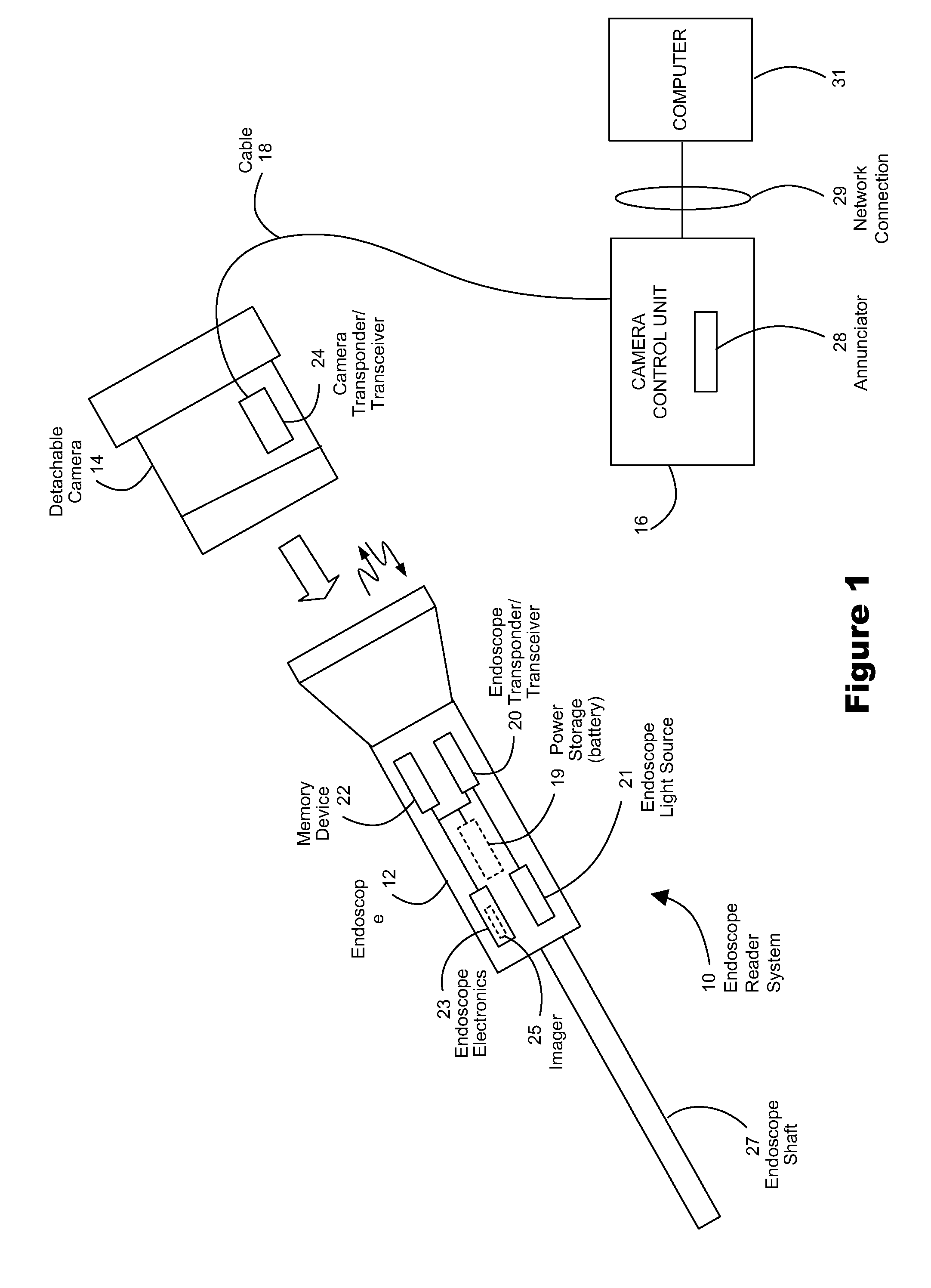
[0051]FIG. 1 illustrates an endoscope system 10 for wirelessly transmitting energy and data, including, for example, storing and transmitting electronic representations of endoscope characteristics. In accordance with one advantageous embodiment, an endoscope transponder / transceiver 20 is mounted on an endoscope 12 and communicates with a camera head transponder / transceiver 24 mounted on a detachable camera head 14. Endoscope transponder / transceiver 20 and camera head transponder / transceiver 24 may be one of any type of relatively short-range devices well known to those of ordinary skill in the art. Endoscope transponder / transceiver 20 and camera head transponder / transceiver 24 are set so that each is capable of both sending and receiving wireless signals to and from the other.

[0052]In one advantageous embodiment, transponder / transceiver 20 and 24 are provided ...


PUM


Abstract

A system for wirelessly powering various devices positioned on an endoscope, including, for example, a light source, various electronics including an imager and/or a memory device. The endoscope is coupled to a camera where the endoscope may be rotated relative to the camera when coupled thereto. The system is further provided such that video signal processing parameters are automatically set for an endoscopic video camera system based upon characteristics of an attached endoscope, with reduced EMI and improved inventory tracking, maintenance and quality assurance, and reducing the necessity for adjustment and alignment of the endoscope and camera to achieve the data transfer.

Description

CROSS-REFERENCE TO RELATED APPLICATIONS[0001]This application is a continuation-in-part application of pending U.S. patent application Ser. No. 12 / 533,545 filed Jul. 31, 2009, which is a continuation-in-part application of pending U.S. patent application Ser. No. 11 / 542,461 filed Oct. 3, 2006, which is a continuation-in-part application of U.S. patent application Ser. No. 10 / 095,616 filed Mar. 12, 2002, now U.S. Pat. No. 7,289,139 issued on Oct. 30, 2007.FIELD OF THE INVENTION[0002]The invention relates to endoscope video camera systems, where the video camera electronically identifies an attached endoscope and automatically sets system parameters in accordance with certain endoscope parameters and wirelessly provides power to the endoscope. The endoscope may be electronically identified for manipulating, (i.e., reading information from, updating and then writing information to the endoscope) for the purposes of endoscope use and maintenance, inventory tracking and control, and moni...

Claims


Application Information

Patent Timeline
IPC IPC(8): H04N7/18
CPCA61B1/00006H04N5/2252A61B1/0002A61B1/00029A61B1/00034A61B1/00055A61B1/00059A61B1/00062A61B1/00128A61B1/042A61B1/045A61B1/05A61B1/0676A61B1/0684A61B2560/0214A61B2560/0276G02B23/2484H04N5/23203H04N5/23209H04N7/181H04N2005/2255A61B1/00064A61B1/00016H04N23/555H04N23/66H04N23/663H04N23/51
Inventor AMLING, MARC R.HOEG, HANS DAVIDCHATENEVER, DAVIDANKNER, CHARLES E.
Owner KARL STORZ IMAGING INC
Why Eureka
Try Eureka