
High flux high efficiency nanofiber membranes and methods of production thereof

a nanofiber membrane and high-efficiency technology, applied in the field of nanofiber filtration, can solve the problems of reducing the diameter of the fiber, using highly corrosive reagents, and difficult electrospinning process to prepare a nanofiber

Inactive Publication Date: 2011-08-18
THE RES FOUND OF STATE UNIV OF NEW YORK
View PDF8 Cites 79 Cited by
  • Summary
  • Abstract
  • Description
  • Claims
  • Application Information

AI Technical Summary

Benefits of technology

[0043]According to a further aspect of the present invention, a method is provided for producing a membrane. A coating layer is produced having a non-woven structure format from polysaccharide nanofibers. The polysaccharide nanofibers have a diameter between 5 to 50 nanometers (nm). An electrospun substrate is immersed into a water-based solution. The coating layer is applied to the electrospun substrate. A gel barrier is formed at an interface between the electrospun substrate and the coating layer to slow diffusion of the coating layer into the electrospun substrate. Nanofibers of the electrospun substrate have a diameter greater than that of the cellulose nanofibers. The electrospun substrate is disposed on a non-woven support having microfibers with a diameter greater than that of the nanofibers of the electrospun substrate.

Problems solved by technology

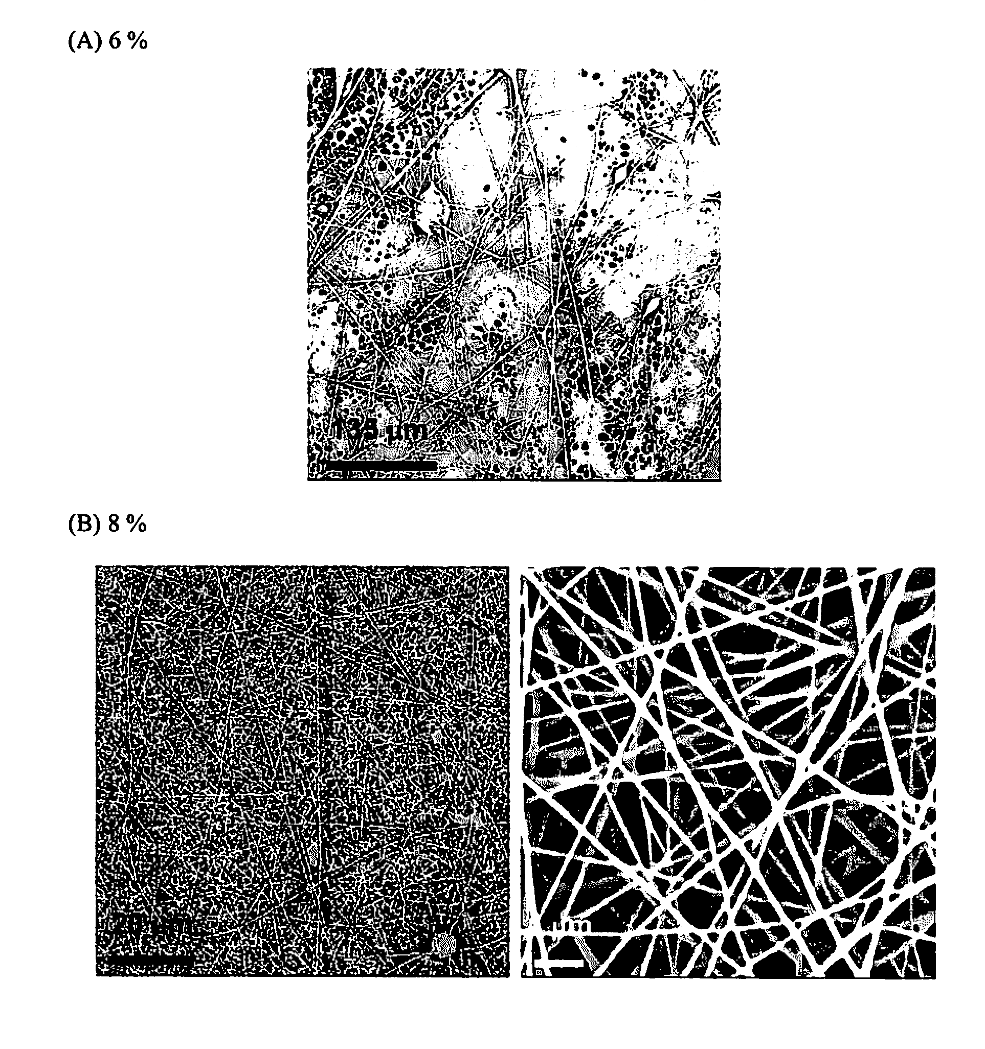
However, it is difficult for the electrospinning process to prepare a nanofiber having a diameter that is less than 50 nm.
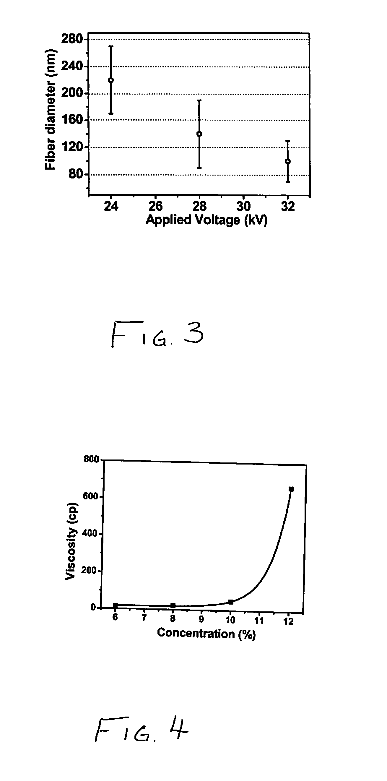
Higher conductivity increases the stretching forces of the electric field on the polymer, which typically results in a decreased fiber diameter.
However, the increasing intermolecular forces of the polymer solution, represented by increasing viscosity, counteract the stretching of the polymer.
Moreover, many of the steps often used highly corrosive reagents, such as strong acids and alkali.
The cryo-crushing and defibrillation processes require special devices, which can seriously affect the extension of this method for large scale operations.
However, such cellulose nanofibers have higher fiber diameter in an approximate range of 300 to 1000 nm, and the process includes an additional post-treatment step using either a toxic or volatile reagent.

Method used


Image

  • High flux high efficiency nanofiber membranes and methods of production thereof
  • High flux high efficiency nanofiber membranes and methods of production thereof
  • High flux high efficiency nanofiber membranes and methods of production thereof

Examples


Embodiment Construction

[0126]Embodiments of the present invention are described in detail with reference to the accompanying drawings. The same or similar components may be designated by the same or similar reference numerals although they are illustrated in different drawings. Detailed descriptions of constructions or processes known in the art may be omitted to avoid obscuring the subject matter of the present invention.

[0127]The terms and words used in the following description and claims are not limited to their dictionary meanings, but are used to enable a clear and consistent understanding of the invention. Accordingly, it should be apparent to those skilled in the art that the following description of embodiments of the present invention are provided for illustrative purposes only and not for the purpose of limiting the invention, as defined by the appended claims and their equivalents.

[0128]It is to be understood that the singular forms “a,”“an,” and “the” include plural referents unless the conte...


PUM

PropertyMeasurementUnit
diameteraaaaaaaaaa
diameteraaaaaaaaaa
diameteraaaaaaaaaa

Abstract

A membrane is provided including a coating layer having cellulose nanofibers produced from oxidized cellulose microfibers and an electrospun substrate upon which the coating layer is applied. The nanofibers of the electrospun substrate have a diameter greater than that of the cellulose nanofibers. The membrane also has non-woven support upon which the electrospun substrate is disposed. Microfibers of the non-woven support have a diameter greater than that of the nanofibers of the electrospun substrate. Application of electrospun membrane is in microfiltration area, while the cellulose nanofiber membrane serves in ultra-filtration, nanofiltration, and reverse osmosis after chemical modification.

Description

PRIORITY[0001]This application claims priority under 35 U.S.C. §119(e) to provisional applications filed in the U.S. Patent and Trademark Office on Oct. 7, 2008, Feb. 19, 2009, and Feb. 19, 2009, respectively assigned Ser. Nos. 61 / 103,479, 61 / 153,666 and 61 / 153,669, the contents of which are incorporated herein by reference.GOVERNMENT RIGHTS[0002]The invention of the present application was made with government support under grant number N0014-03-1-0932 awarded by the Office of Naval Research. The government has certain rights in the invention.BACKGROUND OF THE INVENTION[0003]1. Field of the Invention[0004]The present invention relates generally to nanofiber filtration and, more particularly, to a three-layer filter membrane having a top coating layer with cellulose nanofibers.[0005]2. Description of the Related Art[0006]The present application is related to Publication No. US 2009 / 0078640 A1 of U.S. patent application Ser. No. 12 / 126,732, filed May 23, 2008, and provisional applica...

Claims


Application Information

Patent Timeline
Patent Type & Authority Applications(United States)
IPC IPC(8): B01D71/08B05D1/18B05D3/02B01D67/00B01D71/12B01D69/10
CPCB01D39/1615Y10T428/2495B01D39/18B01D67/0002B01D71/12B01D2239/025B01D2239/0478B01D2239/0631B01D2239/0654B01D2239/10B01D2239/1208B01D2239/1216B01D2239/1233D01D5/0084D01F2/00D01F2/24D06M13/123D06M15/263D06M17/00B01D2323/39B01D39/1623Y10T428/249921B01D71/381B01D69/1071
Inventor CHU, BENJAMINHSIAO, BENJAMIN S.MA, HONGYANG
Owner THE RES FOUND OF STATE UNIV OF NEW YORK
Learn More