Wireless antenna for RFID tires

a technology of conductive rubber and wireless antenna, which is applied in loop antennas, instruments, transportation and packaging, etc., can solve the problem of reducing the effective range of the antenna, and achieve the effect of preventing the conductive rubber from discharging the energy being conducted by the antenna

Active Publication Date: 2011-08-18
THE GOODYEAR TIRE & RUBBER CO
View PDF19 Cites 27 Cited by
  • Summary
  • Abstract
  • Description
  • Claims
  • Application Information

AI Technical Summary

Benefits of technology

[0005]The RFID device of the present invention utilizes a wireless antenna of conductive rubber along with a computer chip and is embedded in the body of a tire or affixed to the inner surface of the tire. The antenna is formed of electrically conductive green rubber encapsulated in insulation formed by a pair of non-conducting green rubber sheets adhered together. The insulation preferably is a non-conducting green rubber but could be non-conducting rubber or other materials having properties suitable for integration within the rubber tire. Other materials which may be utilized for the insulation include an elastomer or rubber minus the carbon black which is the conductive component. The insulation isolates the antenna from the dielectric rubber of the tire and, thereby, prevents the conductive rubber from dissipating the energy being conducted by the antenna.
[0006]The RFID device of the present invention utilizes a standard computer chip, preferably an EPC1 GEN2 RFID chip of less than one millimeter (1 mm)×one millimeter in size. The RFID chip is coupled with a conductive rubber dipole or slot antenna. Under one embodiment, conductive adhesives and / or other encapsulates maybe utilized to improve the interface between the chip mounting and the rubber antenna thus improving the performance. In this case, cured or vulcanized rubber rather than green rubber could be used for the antenna. If green rubber is used for the antenna, it is not necessary to use adhesive as the natural stickiness of the green rubber will cause it to adhere to the surface of the insulating layer engaged thereto. On the other hand, it is possible to use adhesive with an antenna of green rubber in order to provide a more effective seal. The sub-assembly of the rubber antenna and the computer chip is enclosed in a non-conductive rubber envelope or sheets. The current technology allows for the rubber antenna to be an integral component of the tire with no concerns of destroying the integrity of the tire.
[0007]Preferably the RFID device of the present invention is produced in the uncured state. It is affixed to the inner or outer surface of the tire in the green state. It may also be embedded in the tires, between the plies. Following such affixing or embedding, it is vulcanized along with the rest of the tire. However, it could also be vulcanized and then affixed following vulcanization of the tire or assembled using vulcanized conductive rubber and then affixed to the tire. The installed RFID devices will allow improved quality, sorting of tires on conveyors and tracking of shipments.
[0009]The antenna of the RFID device of the present invention has a conductive rubber compound which has been developed for its conductivity to get into the range of 20 ohms to 400 ohms per inch of rubber. Resistances in the range of 40-100 ohms per inch are suitable for use as an antenna. The non-conductive rubber is utilized as an electrical insulator which isolates the antenna from the rubber of the tire. The encapsulation in the non-conductive rubber causes the antenna to stay in tune with the RFID microchip, which allows for the long range read characteristics.

Problems solved by technology

Unless properly insulated, the conductive characteristics of the tire rubber will de-tune the antenna of the RFID device which greatly reduces its effective range.

Method used


Image

  • Wireless antenna for RFID tires
  • Wireless antenna for RFID tires
  • Wireless antenna for RFID tires

Examples


Embodiment Construction

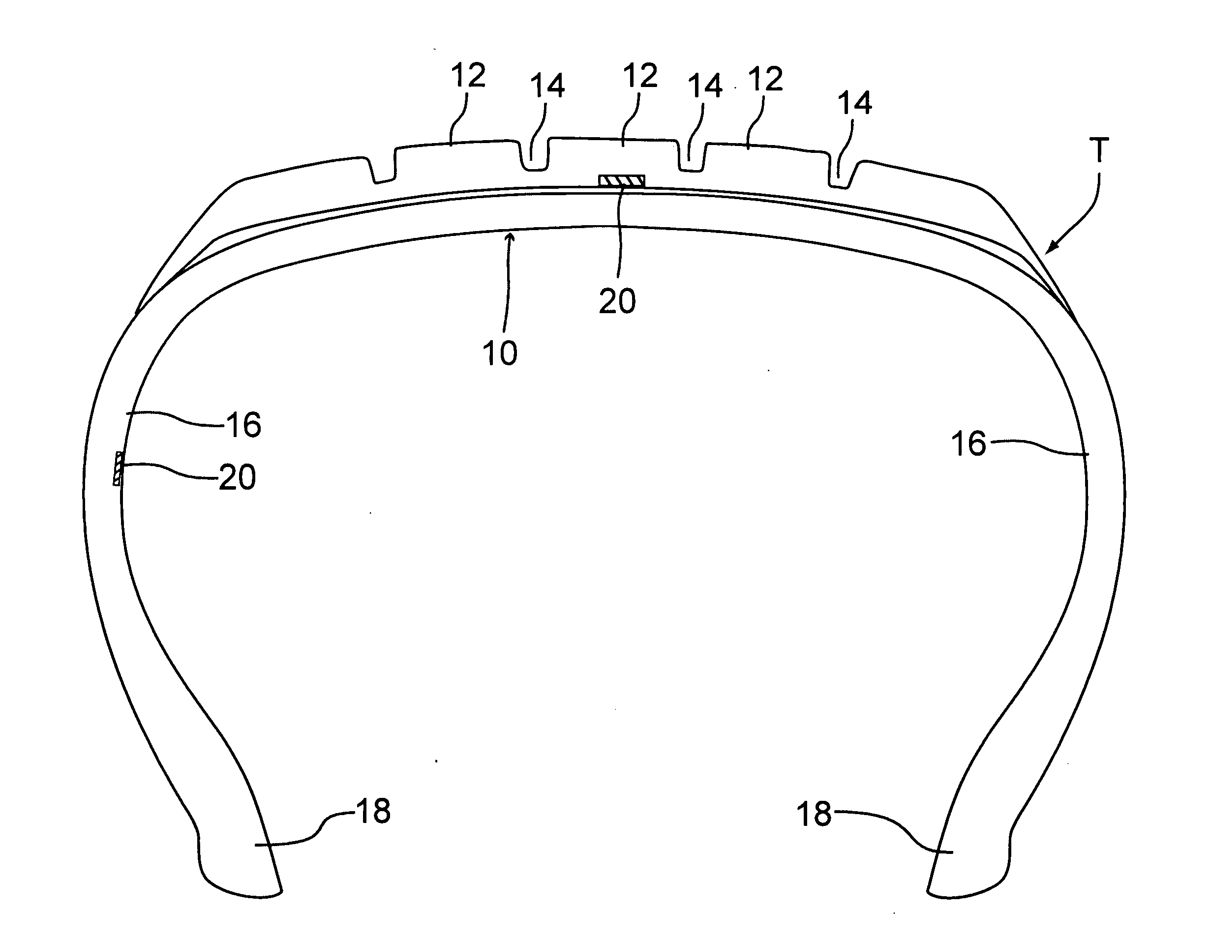
[0017]Referring to FIG. 1 there is shown a tire T having a crown 10 with external treads 12 and grooves 14. In cross-section the tire T has the crown 10 extending radially outwardly along an arcuate path to a pair of oppositely disposed sidewalls 16 which define the maximum radial extent of the tire T. The sidewalls 16 curve inwardly from such maximum radial extent to a narrower area terminating at a pair of oppositely disposed beads 18. As shown in FIG. 1 there is provided an RFID device 20 of the present invention which is permanently embedded either in the crown 10 or in one of the sidewalls 16. It may also be adhered to the inner surface of the tire in the area of the crown 10 or the sidewall 16.

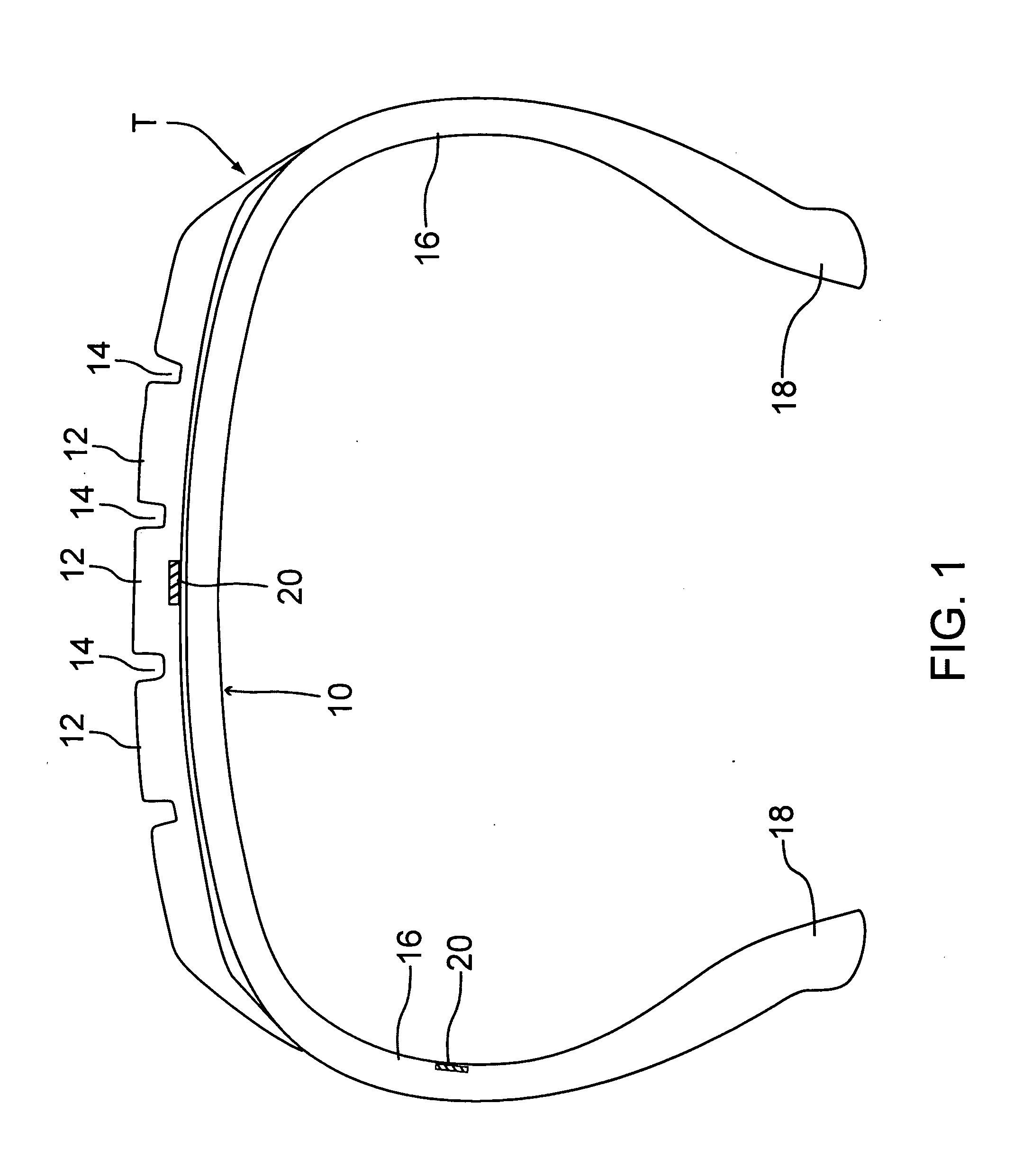
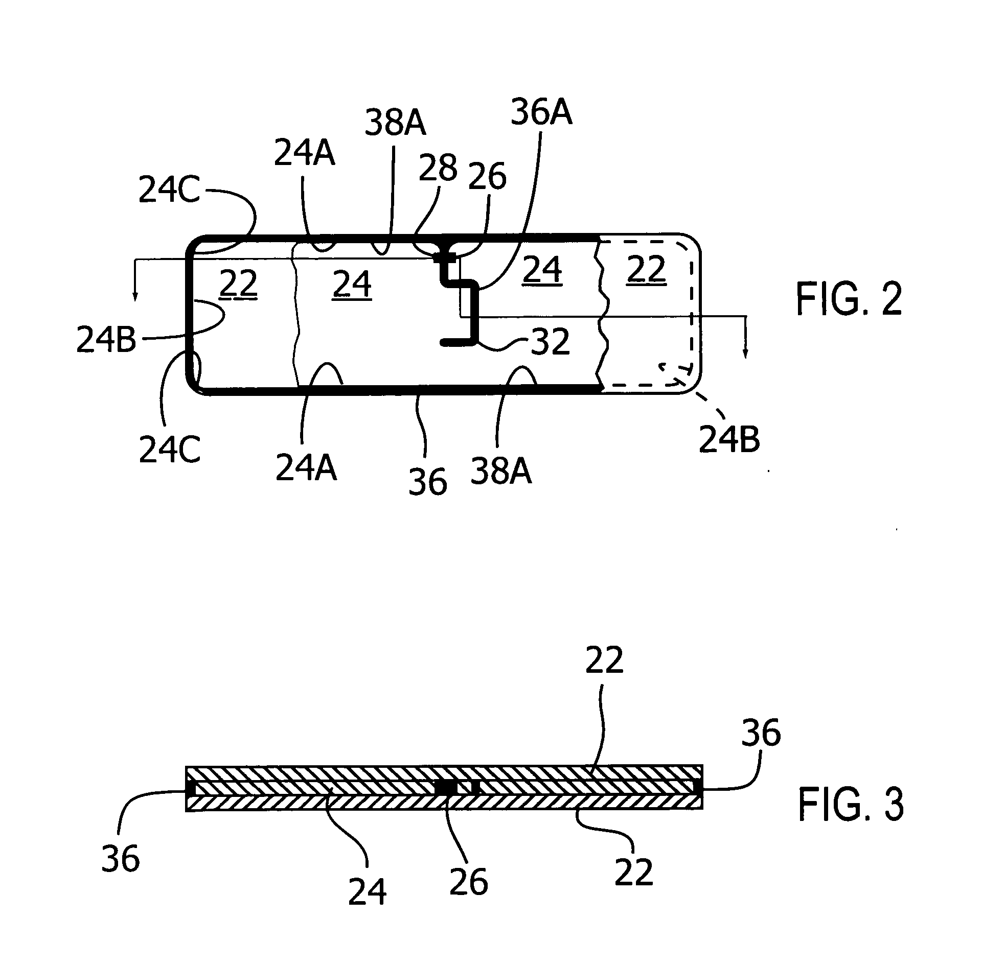
[0018]Referring to FIGS. 2, 3 and 4, the RFID device includes a pair of insulation members 22 and an antenna 24 encapsulated therebetween. A RFID microchip 26 such as EPC1 GEN has tabs 28 attached to the antenna 24. The antenna 24, which may be one of a number of shapes, is shown as a re...


PUM

PropertyMeasurementUnit
electrical resistanceaaaaaaaaaa
thicknessaaaaaaaaaa

Abstract

An RFID device for tires utilizes a wireless antenna. The antenna is formed of a pair of spaced apart electrically conductive rubber units. The conductive rubber antenna is encapsulated between a pair of non-conductive sheets. A third non-conductive member encircles the conductive rubber antenna and is itself sealed between the first and second sheets of non-conductive material. A microchip is positioned in the slot defined by the space between the units and conductively attached to each of the units.

Description

CROSS REFERENCE TO RELATED APPLICATIONS[0001]This application is based upon and claims the benefit of U.S. Provisional Patent Application No. 61 / 337,933 filed Feb. 12, 2010 and is a continuation in part of U.S. patent application Ser. No. 12 / 806,726 filed Aug. 18, 2010.BACKGROUND OF THE INVENTION[0002]The use of radio frequency identification devices (RFID) in tires is gaining in popularity. See for example my issued U.S. Pat. No. 7,504,947. Other devices, including RFID devices, which may be incorporated on a surface of or within the structure of a tire for monitoring various functions relative to the tire include the following U.S. Pat. Nos. 5,562,787; 5,741,966; 6,062,072; 6,856,245; 6,897,770; 7,009,576; and 7,186,308. The disclosures contained in these patents are incorporated herein by reference.[0003]U.S. Pat. No. 7,009,576 discloses a tire having a radio frequency antenna embedded therein. Since the rubber in which the radio frequency antenna is embedded is in a mixture of r...

Claims


Application Information

Patent Timeline
Patent Type & Authority Applications(United States)
IPC IPC(8): G06K19/077H05K13/00
CPCB60C23/0452B60C23/0493G06K19/02G06K19/041Y10T29/49002G06K19/07764H01Q1/2241H01Q1/3233H01Q7/00G06K19/07749
Inventor TUCKER, RANDALL L.
Owner THE GOODYEAR TIRE & RUBBER CO
Why Eureka
Try Eureka