Ultraviolet light exposure chamber for photovoltaic modules

a photovoltaic module and ultraviolet light technology, applied in the field of ultraviolet light exposure chambers for photovoltaic modules, can solve the problem of less than a factor of two reduction in exposure intensity, and achieve the effect of reducing exposure intensity, reducing uv exposure intensity, and accelerating testing

Active Publication Date: 2011-08-18
ATONOMETRICS
View PDF11 Cites 16 Cited by
  • Summary
  • Abstract
  • Description
  • Claims
  • Application Information

AI Technical Summary

Benefits of technology

[0012]In another embodiment, the apparatus includes two target planes, one on either side of the lamp array. The use of two target planes reduces the UV exposure intensity that may be achieved at one test sample as compared with the embodiment involving one target plane only and a back-reflector positioned behind the lamps. However, the reduction in exposure intensity is less than a factor of two—since the efficiency of a back reflector is less than 100%—while the additional target plane allows simultaneous exposure of twice as many samples.
[0013]In yet another embodiment, a system designed to use two target planes may be operated with test modules mounted on one target plane only. Reflectors could be included on at least one of the target planes so that when no test modules are present on that plane, light intensity at the other plane is increased and testing is accelerated.
[0014]In one embodiment, the reflective panels include flat side reflectors and / or flat top and bottom reflectors. Side reflectors provide for improved horizontal uniformity of UV irradiance at the target plane(s), while top and bottom reflectors provide for improved vertical uniformity of UV irradiance at the target plane(s).
[0015]In an alternative embodiment, the system includes curved reflectors (or collections of flat reflectors approximating curved reflectors) at the top and bottom of the chamber to provide for improved vertical uniformity of UV irradiance at the target plane(s) compared to flat top and bottom reflectors by increasing the irradiance intensity near the top and bottom of the target plane(s) and decreasing the irradiance intensity near the center of the target plane(s).
[0016]In one embodiment, lamps near each side reflector are positioned closer to the target plane(s) than lamps in the interior portion of the lamp array, providing improved horizontal uniformity of the UV irradiance at the target plane(s) by compensating for reflective losses at the side reflectors.

Problems solved by technology

However, the reduction in exposure intensity is less than a factor of two—since the efficiency of a back reflector is less than 100%—while the additional target plane allows simultaneous exposure of twice as many samples.

Method used


Image

  • Ultraviolet light exposure chamber for photovoltaic modules
  • Ultraviolet light exposure chamber for photovoltaic modules
  • Ultraviolet light exposure chamber for photovoltaic modules

Examples


Embodiment Construction

[0033]Although described with particular reference to UV testing of photovoltaic modules, those with skill in the arts will recognize that the disclosed embodiments have relevance to a wide variety of areas in addition to those specific examples described below.

[0034]All references, including publications, patent applications, and patents, cited herein are hereby incorporated by reference to the same extent as if each reference were individually and specifically indicated to be incorporated by reference and were set forth in its entirety herein.
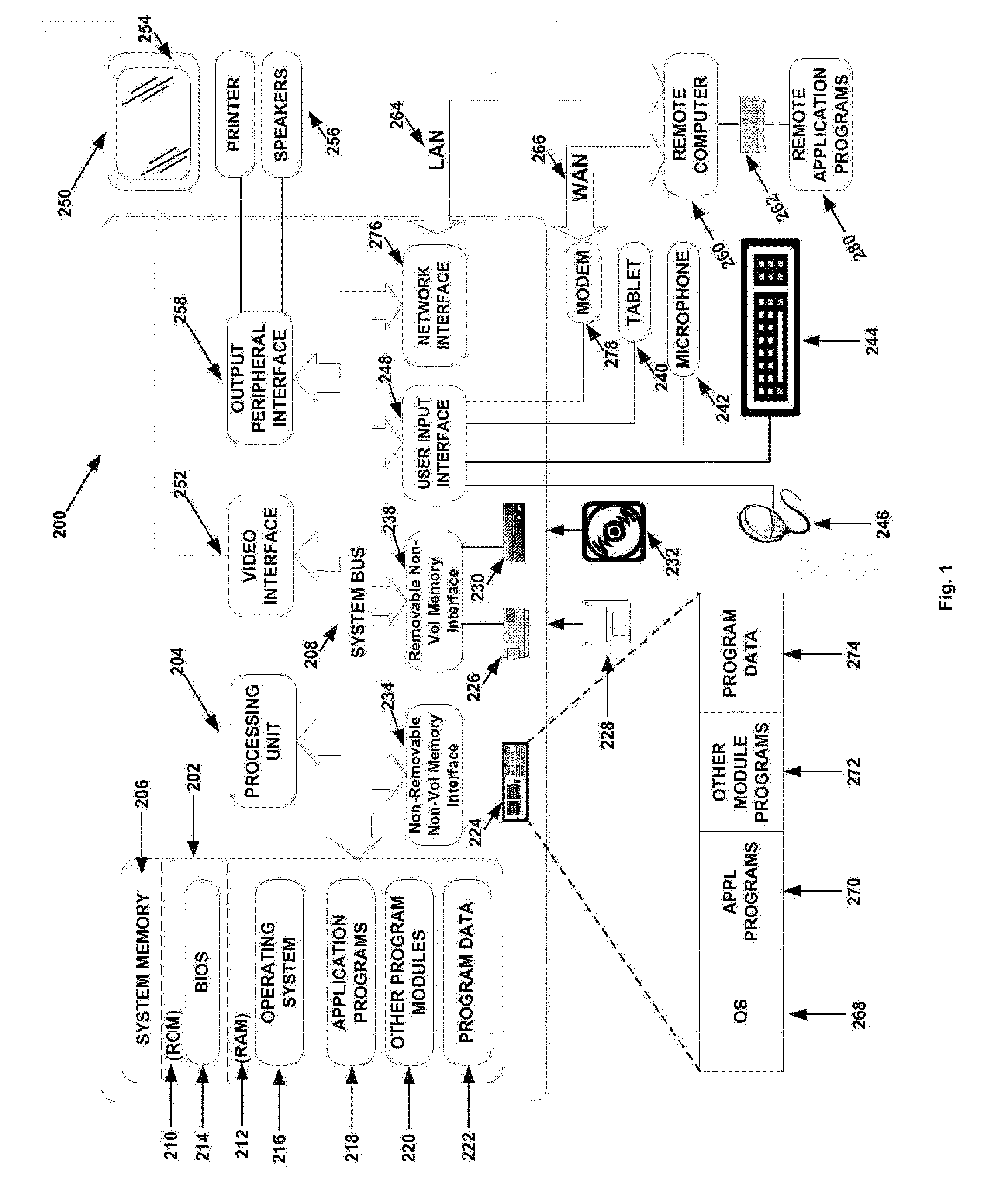
Computing System

[0035]With reference to FIG. 1, an exemplary system within a computing environment for implementing the invention includes a general purpose computing device in the form of a computing system 200, commercially available from Intel, IBM, AMD, Motorola, Cyrix and others. Components of the computing system 202 may include, but are not limited to, a processing unit 204, a system memory 206, and a system bus 236 that couples variou...


PUM


Abstract

An apparatus for performing UV light exposure testing of solar panels, also known as PV modules, with superior exposure uniformity, equipment throughput, and floor space requirements, consisting of a chamber including a plurality of UV lamps in a lamp array, at least one target plane, and reflective panels positioned within the chamber to redirect UV light to the target plane(s).

Description

RELATED APPLICATION DATA[0001]The present U.S. Utility Patent Application claims priority pursuant to 35 U.S.C. §371, as a national application, to the following International Application which is hereby incorporated herein by reference in its entirety and made part of the present U.S. Utility Patent Application for all purposes:[0002]1. International Application Serial No. PCT / US2009 / 060967, entitled “ULTRAVIOLET LIGHT EXPOSURE CHAMBER FOR PHOTOVOLTAIC MODULES,” (Attorney Docket No. ATON002WO), filed Oct. 16, 2009, which claims priority pursuant to 35 U.S.C. §119(e) to the following U.S. Provisional Patent Application which is hereby incorporated herein by reference in its entirety and made part of the present U.S. Utility Patent Application for all purposes:[0003]a. U.S. Provisional Application Serial No. 61 / 106,311, entitled “ULTRAVIOLET LIGHT EXPOSURE CHAMBER FOR PHOTOVOLTAIC MODULES,” (Attorney Docket No. ATON002USP, filed Oct. 17, 2008, which is incorporated herein by referenc...

Claims


Application Information

Patent Timeline
Patent Type & Authority Applications(United States)
IPC IPC(8): G01J1/42G21K5/00
CPCG01J1/02G01J1/0271G01J1/04G01J1/0414G01R31/2881G01J1/08G01J2001/4266G01R31/2642G01J1/0422
Inventor GOSTEIN, MICHAELSTUEVE, WILLIAM
Owner ATONOMETRICS
Why Eureka
Try Eureka