Array-type ultrasonic vibrator

a technology of ultrasonic vibrators and arrays, which is applied in the field of array-type ultrasonic vibrators, can solve the problems of difficult application of technology and large transmission loss due to wiring capacity, and achieve the effect of simple formation

Active Publication Date: 2011-08-18
KONICA MINOLTA MEDICAL & GRAPHICS INC
View PDF17 Cites 21 Cited by
  • Summary
  • Abstract
  • Description
  • Claims
  • Application Information

AI Technical Summary

Benefits of technology

[0010]The present invention was contrived in view of the above circumstances, and an object thereof is to provide an array-type ultrasonic vibrator that is capable of simply forming signal wiring without using additional components.

Problems solved by technology

Moreover, finely arranging the elements two-dimensionally increases the output impedance of the piezoelectric elements, causing great transmission loss due to the wiring capacity.
Therefore, it is difficult to apply the technology disclosed in Patent Document 3 to a device that has, for example, a two-dimensional array of piezoelectric elements or a device that has a laminated structure formed by an organic piezoelectric element and inorganic piezoelectric element.

Method used


Image

  • Array-type ultrasonic vibrator
  • Array-type ultrasonic vibrator
  • Array-type ultrasonic vibrator

Examples


embodiment 1

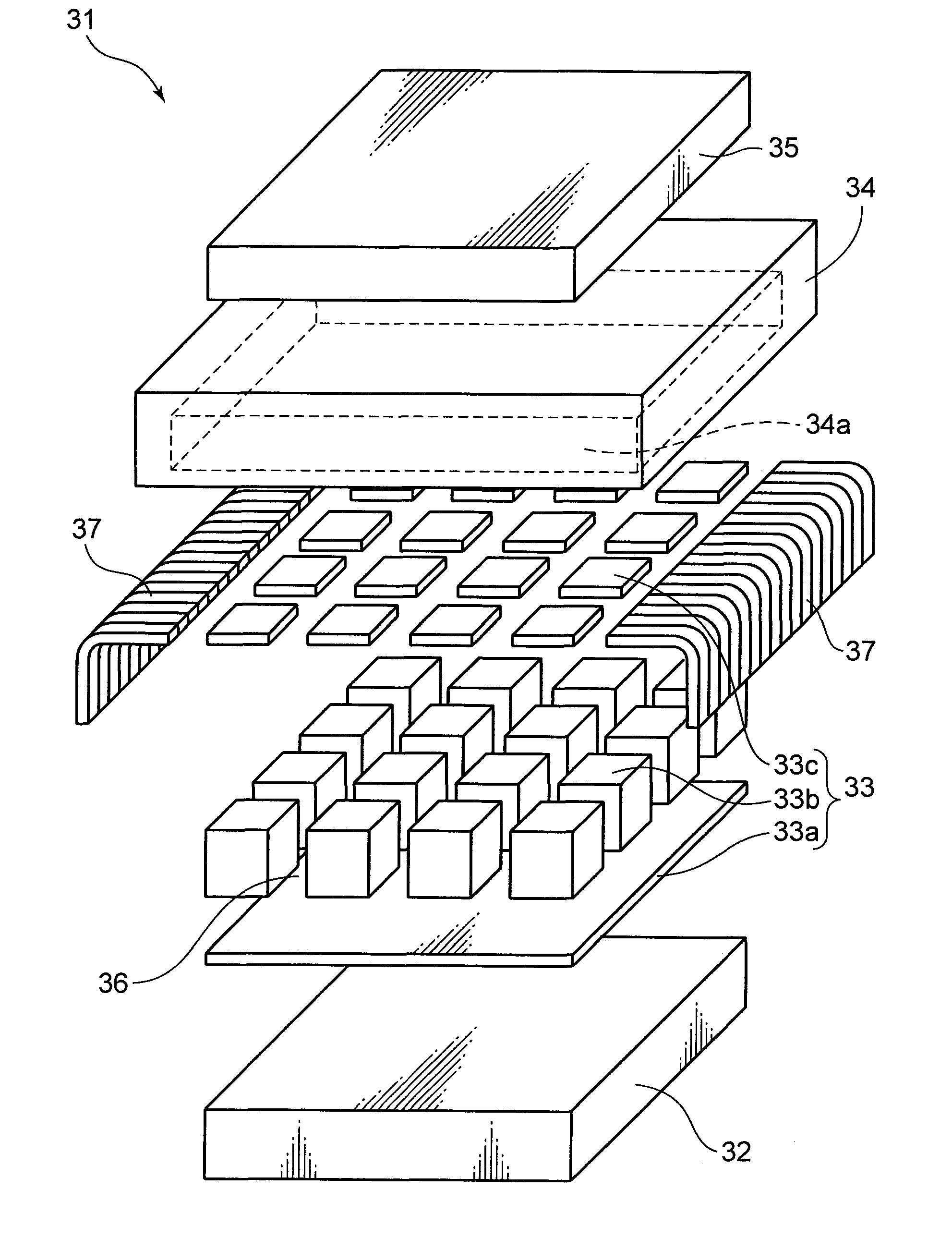
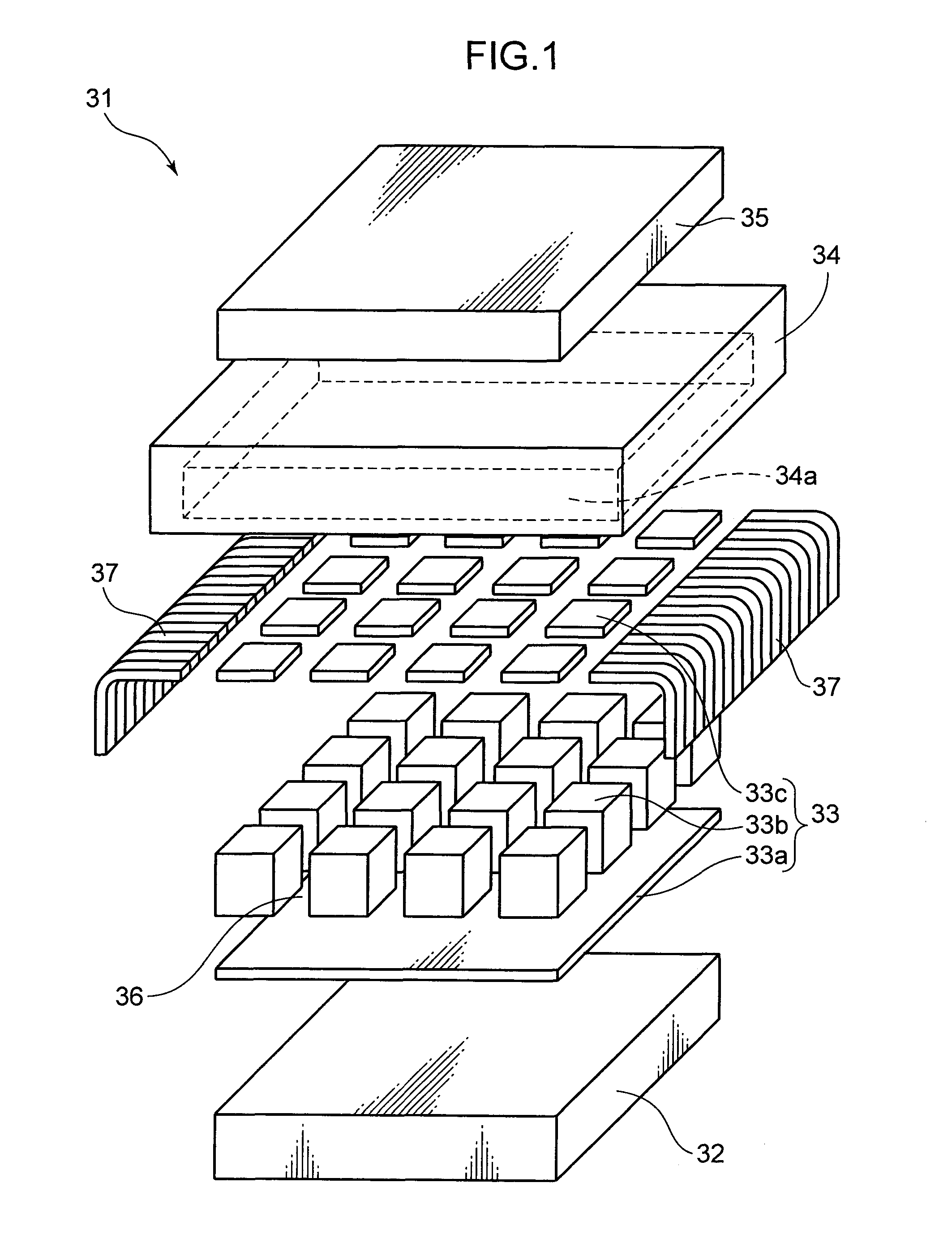
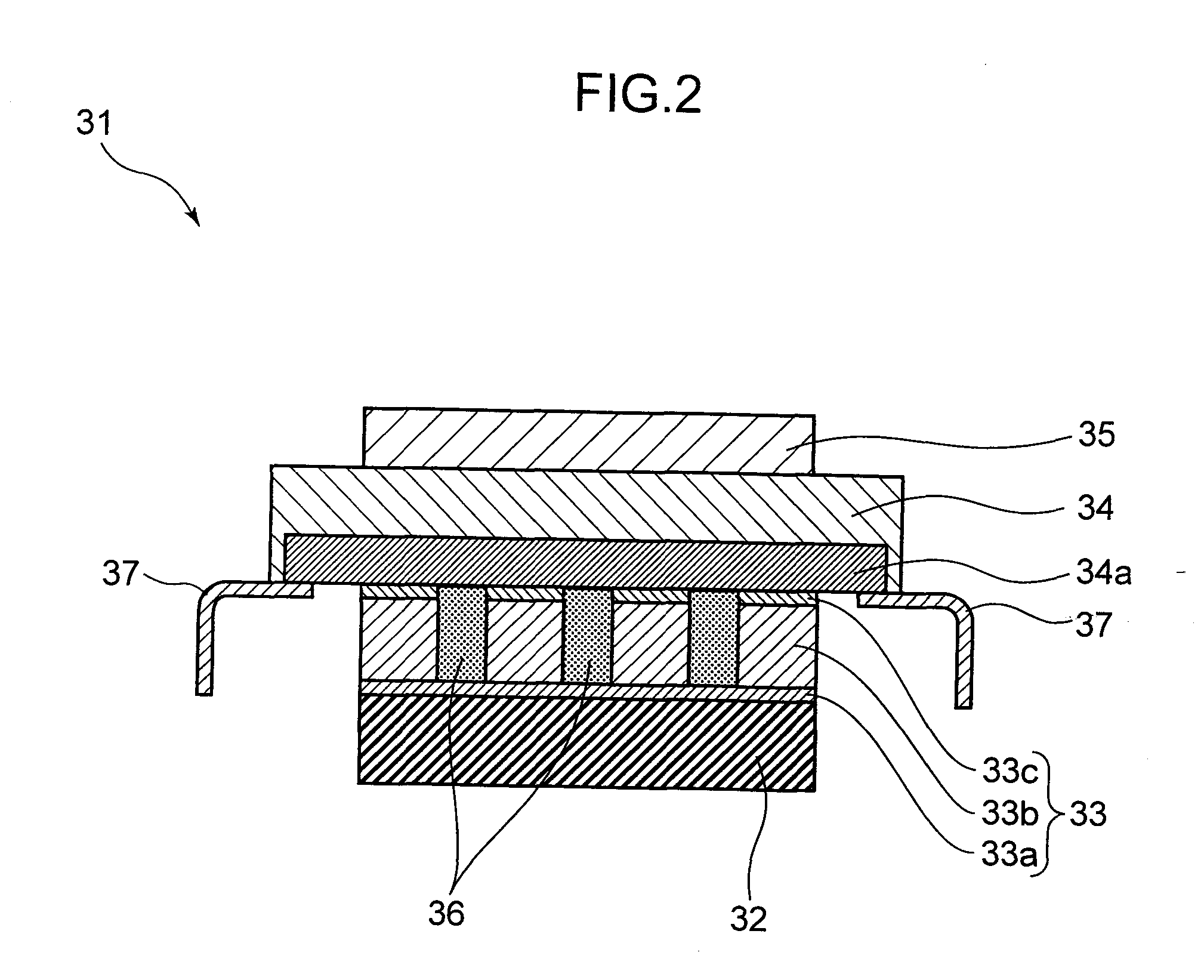
[0029]FIG. 1 is an exploded perspective view showing a structural example of an array-type ultrasonic vibrator 31 according to a first embodiment of the present invention. FIG. 2 is a vertical cross-sectional diagram of this array-type ultrasonic vibrator. In this array-type ultrasonic vibrator 31, basically two acoustic matching layers 34, 35 are laminated on a backing layer 32, in substantially a sound axis direction, via a plurality of piezoelectric element 33 made of ceramic (e.g., lead zirconium titanate; PZT). The plurality of piezoelectric elements 33, arrayed two-dimensionally in the example shown in FIG. 1, are formed as follows: for example, fixing a piezoelectric layer 33b, also made of the ceramic material mentioned above, onto a supporting substrate, not shown; cutting and isolating thus obtained laminated product into a plurality of elements; filling the gaps between the elements with a filler 36; forming a common (GND) electrode 33a thereon, which is then fixed onto t...

embodiment 2

[0040]FIG. 4 is an exploded perspective view showing a structural example of an array-type ultrasonic vibrator 41 according to a second embodiment of the present invention. FIG. 5 is a vertical cross-sectional diagram of this array-type ultrasonic vibrator. In the array-type ultrasonic vibrator 41, a thin layer of piezoelectric elements 44 made of an organic material (e.g., polyvinylidine difluoride; PVDF), capable of receiving a high-frequency signal with a high degree of sensitivity, and a plurality of inorganic piezoelectric elements 43 made of ceramic (e.g., PZT), capable of high-power transmission, are laminated on a backing layer 42. Harmonic imaging is carried out using a harmonic component received by each organic piezoelectric element 44.

[0041]In the inorganic piezoelectric element 43, an individual electrode 43a and a ceramic inorganic piezoelectric layer 43b are laminated on the backing layer 42, and thus obtained laminated structure is separated into pieces (element isol...

embodiment 3

[0045]FIG. 6 is a vertical cross-sectional diagram showing a structural example of an array-type ultrasonic vibrator 51 according to a third embodiment of the present invention. This array-type ultrasonic vibrator 51 is similar to the array-type ultrasonic vibrators 31, 41 described above. Therefore, the same reference numerals are used for indicating the corresponding parts, and the explanations thereof are omitted. In the array-type ultrasonic vibrator 51 of the present embodiment, an acoustic matching layer 52 is configured by a double-sided silicon substrate. The individual signal wiring 46a of the organic piezoelectric layer 44b and the individual signal wiring 34a of the inorganic piezoelectric layer 33b are formed, respectively, on front and rear surfaces of the acoustic matching layer 52. A pattern of the integrated circuit is also formed in the acoustic matching layer 52. Therefore, the backing layer 32 is not provided with the individual signal wiring 47, and the organic p...


PUM


Abstract

An array-type ultrasonic vibrator according to the present invention has an acoustic matching layer that has a plate-like body made of a material having a lower acoustic impedance than a plurality of piezoelectric elements. Signal wiring is formed on the plate-like body of the acoustic matching layer. Accordingly, for this array-type ultrasonic vibrator, the signal wiring can be easily formed without using additional components.

Description

TECHNICAL FIELD[0001]The present invention relates to array-type ultrasonic vibrators for use in, for example, ultrasonic diagnostic apparatuses and is suitably applied to those having a structure having a two-dimensional array of piezoelectric elements, as well as a laminated structure formed by an organic piezoelectric element and inorganic piezoelectric element.BACKGROUND ART[0002]Ultrasonic diagnostic apparatuses have been widely used because of their ability to non-invasively obtain tomographic images of a subject such as a living body. In recent years, there have been apparatuses with a two-dimensional array of piezoelectric elements and apparatuses that obtain high-resolution images by using technology called “harmonic imaging.” Harmonic imaging generates an image that shows an internal state of a subject, by using, not a frequency (fundamental wave) component of an ultrasonic wave transmitted from an ultrasonic probe into a subject, but a harmonic component, which is extract...

Claims


Application Information

Patent Timeline
Patent Type & Authority Applications(United States)
IPC IPC(8): G10K9/125H01L41/09
CPCA61B8/13A61B8/4483G01S15/8927G01S15/8925B06B1/0629
Inventor SATO, KAZUCHIKAHIROSE, SATORUASANO, MASAKI
Owner KONICA MINOLTA MEDICAL & GRAPHICS INC
Why Eureka
Try Eureka