Moving Object, Wireless Power Feeding System, and Wireless Power Feeding Method

a technology of wireless power feeding and moving objects, which is applied in the direction of electric/dynamo-electric converter starters, rail devices, climate sustainability, etc., can solve the problems of low conversion efficiency, inefficient secondary battery charging, and the majority of operators of moving objects, so as to reduce the intensity of radio waves and reduce power loss

Inactive Publication Date: 2011-08-18
SEMICON ENERGY LAB CO LTD
View PDF4 Cites 49 Cited by
  • Summary
  • Abstract
  • Description
  • Claims
  • Application Information

AI Technical Summary

Benefits of technology

[0036]According to one embodiment of the present invention, power can be supplied efficiently from the power feeding device to the moving object, which may result in reduction of power loss ca

Problems solved by technology

That is, misalignment between the positions of the antenna of the power feeding device and the antenna of the moving object leads to a low conversion efficiency, which results in inefficient charging of the secondary battery.
However, it is difficult in most instances for an operator of the moving object to precisely recognize the positional relationship between the antenna of the moving object and the antenna of the power feeding device while driving the moving object, although it depends on where the antennas are installed.

Method used


Image

  • Moving Object, Wireless Power Feeding System, and Wireless Power Feeding Method
  • Moving Object, Wireless Power Feeding System, and Wireless Power Feeding Method
  • Moving Object, Wireless Power Feeding System, and Wireless Power Feeding Method

Examples


embodiment 1

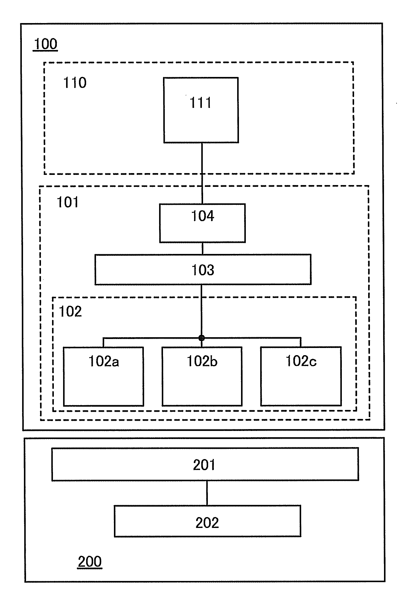
[0060]A structure of a moving object and a wireless power feeding system using the moving object and a power feeding device according to the first structure of the present invention are shown in a block diagram of FIG. 1 by way of an example. Although the block diagram shows separate elements within the moving object or the power feeding device according to their functions, as independent blocks, it may be practically difficult to completely separate the elements according to their functions and, in some cases, one element may involve a plurality of functions.

[0061]As shown in FIG. 1, a moving object 100 includes a power receiving device portion 101 and a power load portion 110. The power receiving device portion 101 includes at least a plurality of moving object antenna circuits of a moving object antenna circuit 102, a signal processing circuit 103, and a secondary battery 104. The power load portion 110 includes at least an electric motor 111. There is no particular limitation on...

embodiment 2

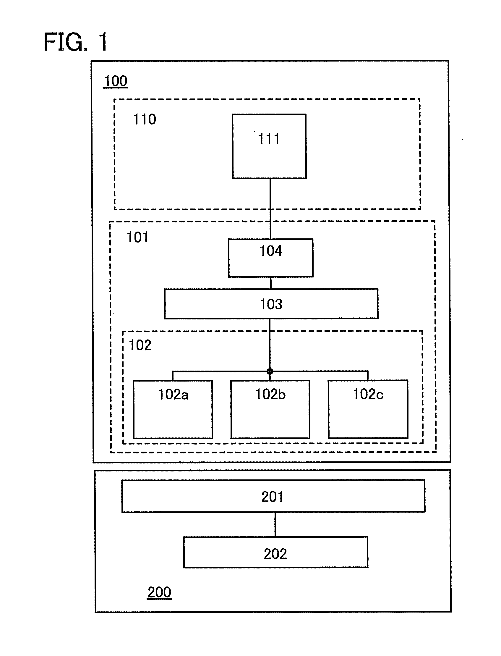
[0082]A structure of a moving object and a wireless power feeding system using the moving object and a power feeding device according to the third structure of the present invention are shown in a block diagram of FIG. 2 by way of an example.

[0083]In FIG. 2, the moving object 100 includes the power receiving device portion 101 and the power load portion 110 as in FIG. 1. The power receiving device portion 101 includes at least the moving object antenna circuit 102, the signal processing circuit 103, and the secondary battery 104. The power load portion 110 includes at least the electric motor 111.

[0084]FIG. 2 illustrates the case where the moving object antenna circuit 102 has one moving object antenna circuit, as an example; however, it may have a plurality of moving object antenna circuits as in FIG. 1.

[0085]In addition, the power feeding device 200 includes a plurality of power feeding device antenna circuits of the power feeding device antenna circuit 201, the signal processing ...

embodiment 3

[0103]A structure of a moving object and a wireless power feeding system using the moving object and a power feeding device according to the second structure of the present invention are shown in a block diagram of FIG. 3 by way of an example.

[0104]In FIG. 3, the moving object 100 includes the power receiving device portion 101 and the power load portion 110 as in FIG. 1. The power receiving device portion 101 includes at least a plurality of moving object antenna circuits of the moving object antenna circuit 102, the signal processing circuit 103, the secondary battery 104, and a selection circuit 120. The power load portion 110 includes at least the electric motor 111.

[0105]There is no particular limitation on the number of the moving object antenna circuits of the moving object antenna circuit 102 as long as it is plural. FIG. 3 illustrates the case where the moving object antenna circuit 102 includes moving the object antenna circuits 102a to 102c, as an example. At least one of...


PUM


Abstract

An object is to provide a moving object structure capable of reducing power loss caused when power is supplied from a power feeding device to a moving object by wireless communication. Another object is to provide a moving object structure capable of reducing the intensity of radio waves radiated to the surroundings. A moving object having a plurality of antennas receives radio waves transmitted from a power feeding device. At least one of the plurality of antennas is installed apart from the other antenna(s) of the moving object. Then, the radio waves transmitted from the power feeding device are received by all the plurality of antennas and converted into electric energy. Alternatively, the radio waves transmitted from the power feeding device are received by one or more selected from the plurality of antennas and converted into electric energy.

Description

BACKGROUND OF THE INVENTION[0001]1. Field of the Invention[0002]The present invention relates to a moving object which is driven by an electric motor and includes a secondary battery chargeable by wireless communication. The present invention also relates to a wireless power feeding system including a moving object and a power feeding device which supplies power to the moving object through wireless communication. The present invention further relates to a wireless communication method for use in the wireless power feeding system.[0003]2. Description of the Related Art[0004]In recent years, energy saving, creation and storage technologies are attracting more attention because environmental problems such as global warming are becoming more severe. In the case of a moving object with a secondary battery, i.e., a moving object which is driven by an electric motor using power provided from a secondary battery regardless of whether they have two wheels or four wheels, such as an electric...

Claims


Application Information

Patent Timeline
IPC IPC(8): H02J17/00H02K11/00H02J7/00B60L5/00B60M7/00
CPCH02J7/0054Y02T90/122H02J17/00Y02B60/50B60L11/007B60L11/182B60L11/1833B60L2200/10B60L2200/12B60L2200/26Y02T10/7005Y02T90/125Y02T90/12Y02T90/121Y02T90/14H02J7/1407B60L53/12H01M10/44H02J7/00Y02T10/7072B60L50/20B60L53/36H02J50/12H02J50/20H02J50/90H02J7/342B60L53/126B60L53/124Y02T90/16Y02T10/70Y02E60/10H02J50/402H02J50/10H02J50/40B60Y2200/91B60L2200/32B60Y2200/11B60Y2200/13B60Y2200/51B60Y2200/30
Inventor YAMAZAKI, SHUNPEIKOYAMA, JUNSHIONAIRI, YUTAKA
Owner SEMICON ENERGY LAB CO LTD
Why Eureka
Try Eureka