
Spm nanoprobes and the preparation method thereof

a technology of nanoprobes and nano-particles, which is applied in the field of spm nano-particles and the preparation method thereof, can solve the problems of inability to meet the third condition, the limitation of the conventional process of cnt-particle sharpening, and the inability to achieve the imaging of irregularly curved surfaces with the straight cnt-particles

Inactive Publication Date: 2011-08-18
KOREA RES INST OF STANDARDS & SCI
View PDF24 Cites 11 Cited by
  • Summary
  • Abstract
  • Description
  • Claims
  • Application Information

AI Technical Summary

Benefits of technology

[0006]Therefore, an object of the present invention is to provide SPM nanoprobes capable of imaging or measuring a irregularly curved or complicated surface, pattern and / or a frictional or adhesive force thereof and controlling size of a spheroid deposit formed at the end portion of nanoneedle and the ratio of the diameter of the spheroid deposit to that of the nanoneedle arbitrarily.

Problems solved by technology

However, the conventional process of sharpening of the end of probe or tip like semiconductor micromachining had the limitation for improving the aspect ratio of the probe.
Though the above mentioned US patents are satisfactory to the first and second factors, they cannot satisfy the third condition.
Moreover, it is impossible to get imaging the irregularly curved surface with the straight shaped CNT tipped probes.
However, the conventional probes for CD-SPM including those described in the above mentioned documents are inadequate for imaging or measuring frictional and / or adhesive force of the complicated inner space of analyte like bio cell or tissue.
However, it may be difficult to make the specified ball and to bonding it to the end of the nanoneedle at accurate position and direction.
However, the diameter of the Pt ball is no more than 60 nm and the the ratio of the diameter of the Pt ball to that of the nanoneedle is only under 1.4, so that the Pt ball capped nanoprobes described in the above document has the limitation in various use.

Method used


Image

  • Spm nanoprobes and the preparation method thereof
  • Spm nanoprobes and the preparation method thereof
  • Spm nanoprobes and the preparation method thereof

Examples


Embodiment Construction

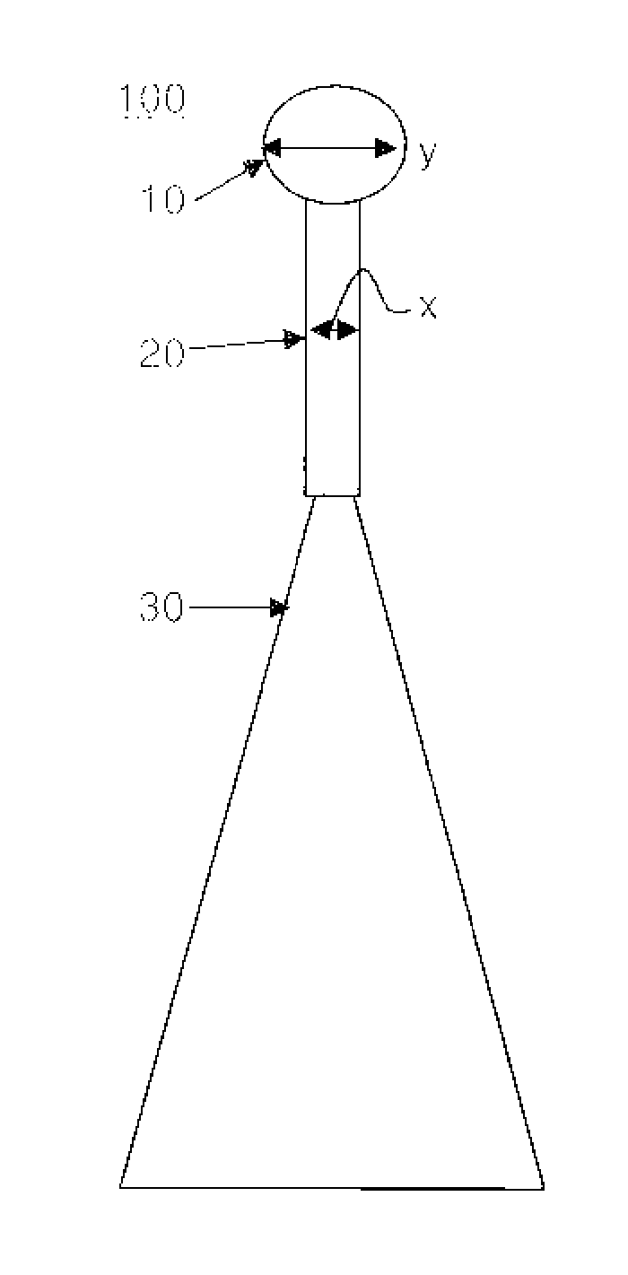
[0028]10: spheroid deposit 20: nanoneedle

[0029]30: mother tip x: diameter of the nanoneedle

[0030]y: diameter of the spheroid deposit 100: SPM nanoprobe

BEST MODE FOR CARRYING OUT THE INVENTION

[0031]Hereinafter, the present invention will be described in more detail through preferred embodiments of the present invention. However, the follow embodiments are provided to aid understanding of the present invention, the present invention is not limited only to the follow embodiments.

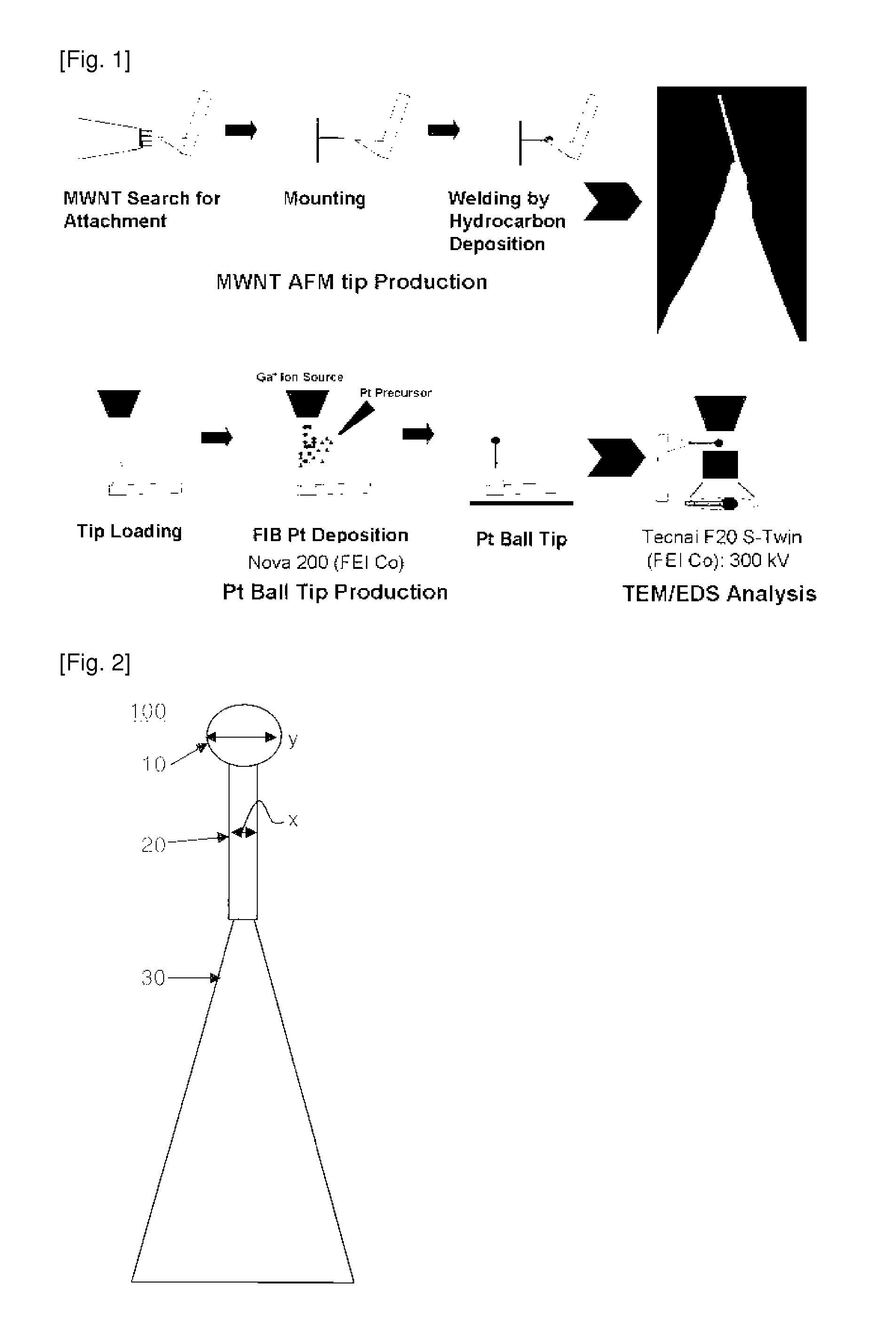
[0032]FIG. 1 is a illustration for preparation process of SPM nanoprobe of the present invention and FIG. 2 is illustrative cross sectional view of SPM nanoprobe of the present invention. As shown in FIGS. 1 and 2, the SPM nanoprobe of the present invention is a probe that a nanoneedle is bonded to an end portion of a mother tip. And also, as shown in FIG. 2 and Korean Patent No. 767994, a bonding of a nanoneedle to a mother tip may be performed by welding of a hydrocarbon deposition.

[0033]Hereinafter, the “nan...


PUM


Abstract

The present invention relates to SPM nanoprobes and the preparation method thereof, more particularly, to SPM nanoprobes comprising a spheroid deposit capped-nanoneedle bonded to one end of a mother tip, wherein the spheroid deposit is formed by particle beam induced deposition and is characterized in that the ratio of the diameter of the spheroid deposit to that of the nanoneedle is in the range of 1.5 to 8.5. The SPM nanoprobe according to the present invention is capable of imaging or measuring an irregularly curved or complicated surface, pattern and / or a frictional or adhesive force thereof and controlling size of a spheroid deposit formed at the end portion of nanoneedle and the ratio of the diameter of the spheroid deposit to that of the nanoneedle arbitrarily.

Description

TECHNICAL FIELD[0001]The present invention relates to a SPM nanoprobe and the preparation method thereof, more particularly, to a SPM nanoprobe comprising a spheroid deposit capped-nanoneedle bonded to one end of a mother tip, wherein the spheroid deposit is formed by particle beam induced deposition and is characterized in that the ratio of the diameter of the spheroid deposit to that of the nanoneedle is in the range of 1.5 to 8.5 and the preparation method thereof.BACKGROUND ART[0002]SPMs (scanning probe microscopes) including AFM (Atomic Force Microscope), MFM (Magnetic force microscope), EFM (electrostatic force microscope), SNOM (scanning near field optical microscope) and LFM (lateral force microscope) are very powerful and useful apparatus in the nano technology. The resolution of SPM is known as atomic scale, however, in order to improve the resolution of SPM, the process of sharpening of the end of probe or tip is required. However, the conventional process of sharpening o...

Claims


Application Information

Patent Timeline
IPC IPC(8): G01Q70/12G01Q70/16B82Y15/00B82Y99/00
CPCB82Y15/00G01Q70/12B82Y35/00G01Q70/16
Inventor AN, SANG JUNGPARK, BUONG CHONKAHNG, YUNG-HOCHOI, JIN HOJEONG, KWANG HOON
Owner KOREA RES INST OF STANDARDS & SCI
Learn More