

Method and system for optimized LNG production
a technology of lng production and optimization method, applied in the direction of refrigeration and liquidation, lighting and heating apparatus, solidification, etc., can solve the problems of less profit and environmental protection, less pipeline dimensions, and energy demand, and achieve the reduction of pipeline dimensions, the specific work and suction volume of the compressor, and the overall system efficiency.
Active Publication Date: 2011-08-25
WARTSILA OIL & GAS SYST
View PDF23 Cites 23 Cited by
- Summary
- Abstract
- Description
- Claims
- Application Information
AI Technical Summary
Benefits of technology
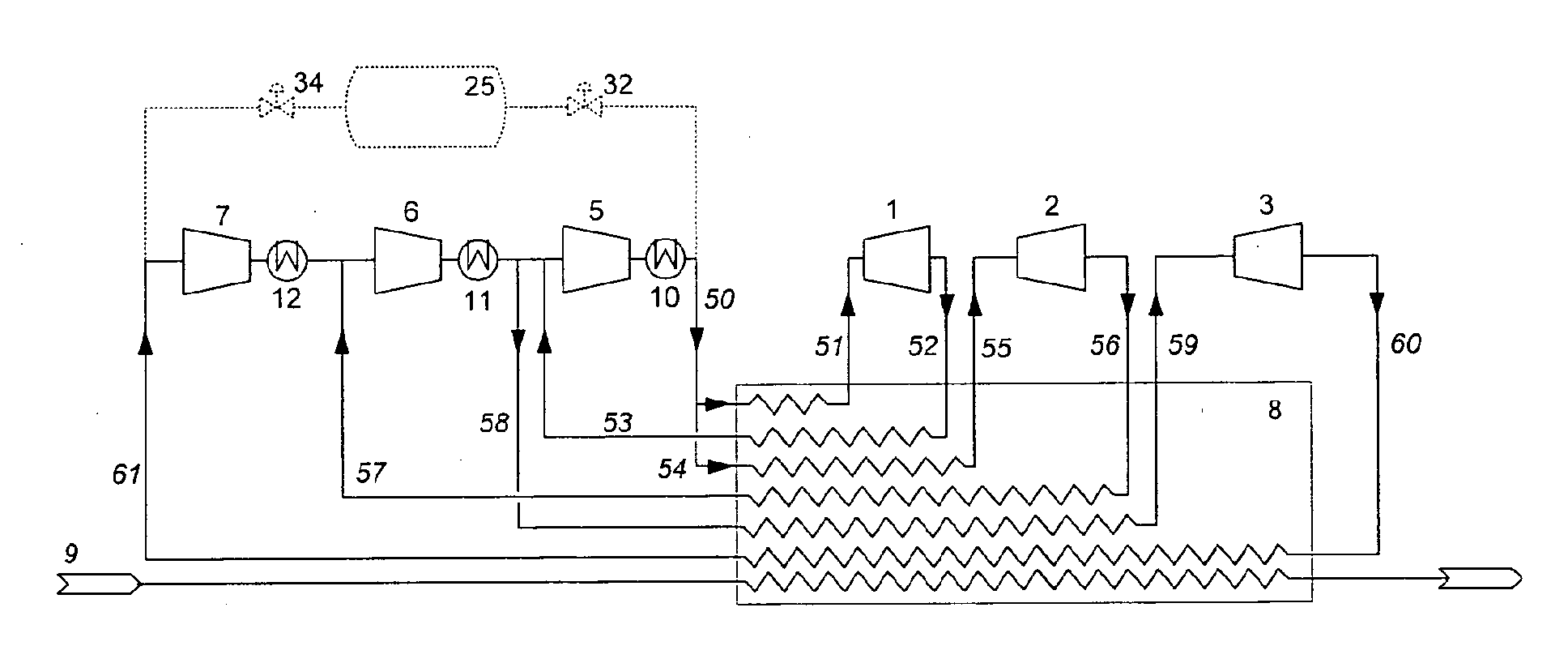
[0011]The current invention relates to a method and apparatus for optimized production of LNG. In order to minimize the specific energy consumption, the heat exchanger losses have to be minimized. This is achieved by arranging at least two expanders in single component and single phase refrigeration cycle(s) so that the mass flows, temperatures and pressure levels into the expanders can be controlled separately. By this arrangement, the refrigeration process can be adapted to varying gas compositions at different pressures and temperatures, and at the same time optimize efficiency. The control is inherently robust and flexible. A LNG production plant according to the present invention can be adapted to different gas sources and at the same time maintain the low specific energy consumption.
[0015]Outlet pressures of the expanders are controlled to be as high as possible but at the same time feeding the heat exchanger arrangement for sub-cooled LNG production with required refrigerant temperatures. Suction pressures for each of the compressor stages are then kept as high as possible. This is unlike prior art, see e.g. U.S. Pat. No. 5,916,260, wherein all streams are expanded down to the lowest refrigerant pressure. A major improvement with the present invention is that specific work and suction volumes of the compressors are minimized, thus improving the overall system efficiency. Pipeline dimensions are reduced with smaller valves and actuators as a consequence. All these factors contribute to a significant cost and space need reduction. Installation work will also become less complicated and hence more efficient.
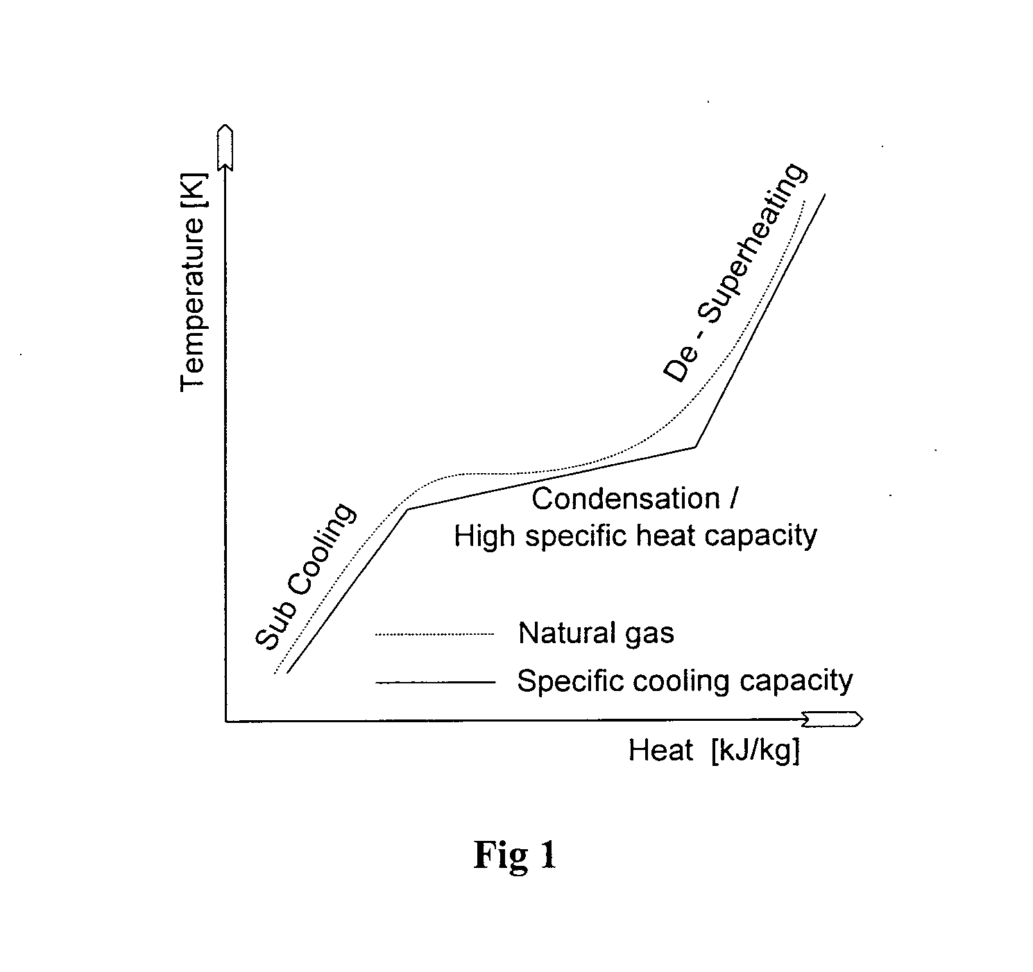
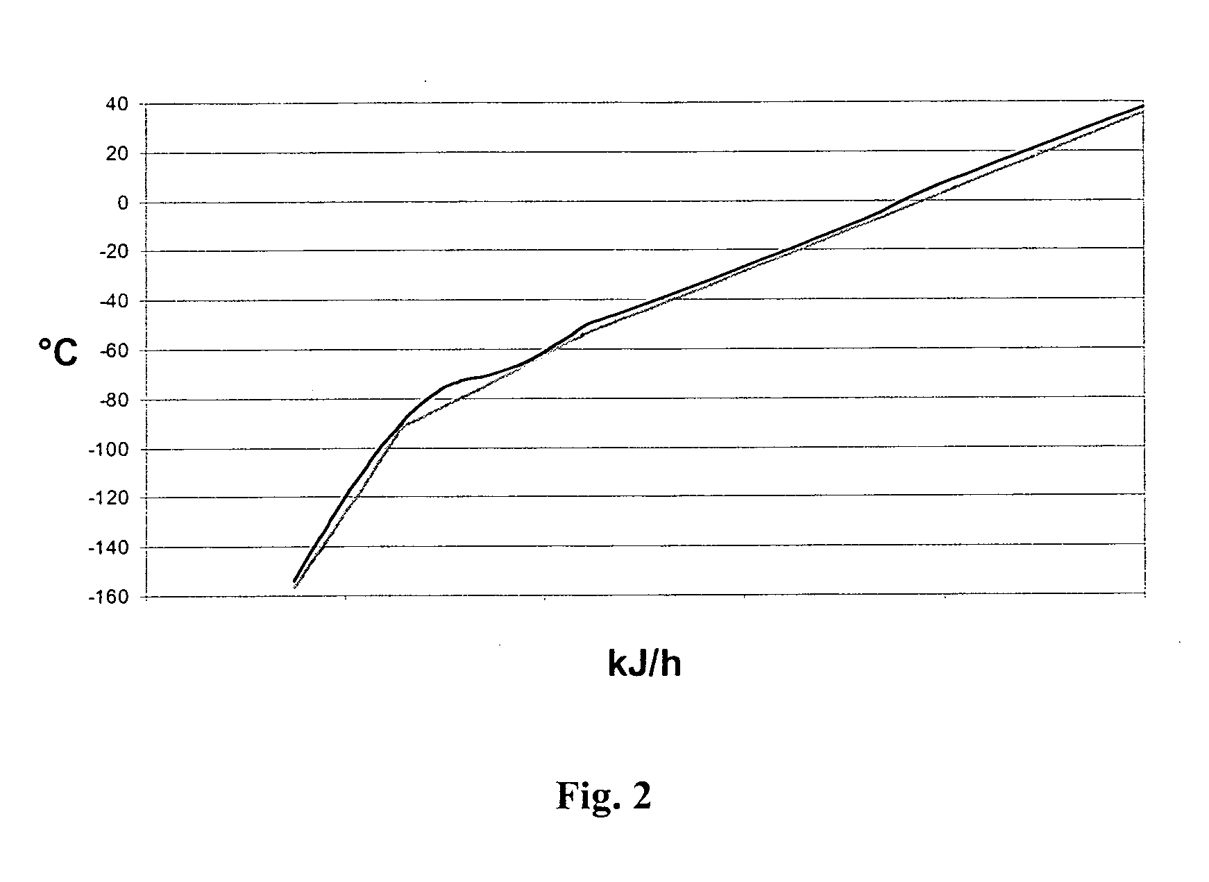
[0016]Reducing heat exchanger losses is of vital importance in low temperature processes. An important embodiment of the present invention is that it reduces the temperature differences to a minimum by adapting the refrigeration process to the principally three different stages of LNG production: de-superheating, condensation (cooling of dense phase at supercritical pressures) and sub-cooling. This is unlike prior art technology, e.g. U.S. Pat. No. 6,412,302, not having separate adaptation for de-superheating and condensation / cooling of dense phase.
[0017]The present invention will operate with single refrigerant in the gas phase. Nitrogen is an obvious alternative. The non-flammability is regarded as an advantage in for instance offshore installations. Using only one single component refrigerant also reduces complexibility.
Problems solved by technology
A challenge on the FPSO's is the space available.
An important issue for LNG production is the energy demand.
High energy demand per kg produced LNG, i.e. specific energy consumption, makes it less profitable and less environmental friendly.
Due to its complexity, MCR-technology is costly and control is slow.
Another disadvantage is that the refrigerant is combustible which may be a problem, especially in offshore installations.
Also using a flammable refrigerant implies restrictions or extra equipment.
Common for these are that heat absorption includes phase change of refrigerant, which inherently gives a more complex system.
More equipment is needed and the control becomes complicated and sensitive.
Method used
View moreImage
Smart ImageViewing Examples

Examples
example
[0049]Applying the present invention, e.g. as shown in FIG. 3 to a typical natural gas source, calculated energy efficiencies of around 0.32 kWh / kg LNG can be achieved, depending on the external conditions. Comparing to prior art solutions, e.g. according to U.S. Pat. No. 6,412,302 which has a calculated energy efficiency of 0.44 kWh / kg LNG at equal ambient condition and based on operational data suggested in this description, it is a significant improvement.
Login to View More PUM
 Abstract
A method and system for producing liquefied and sub-cooled natural gas by means of a refrigeration assembly using a single phase gaseous refrigerant comprising: at least two expanders (1-3); a compressor assembly (5-7); a heat exchanger assembly (8) for heat absorption from natural gas; and a heat rejection assembly (10-12). The novel features according to the present invention are arranging the expanders (1-3) in expander loops; using only one and the same refrigerant in all loops; passing an expanded refrigerant flow from the respective expander into the heat exchanger assembly (8), each being at a mass flow and temperature level adapted to de-superheating, condensation or cooling of dense phase and / or sub-cooling of natural gas; and serving the refrigerant to the respective expander in a compressed flow by means of the compressor assembly having compressors or compressor stages enabling adapted inlet and outlet pressures for the respective expander.
Description
BACKGROUND OF THE INVENTION[0001]The energy demand in the world is increasing, and the forecast is a continued growth. Gas as an energy carrier has received increased attention recent years, and it is predicted that gas will become even more important. In order to transport gas over longer distances, liquefied natural gas, LNG, is often regarded as the best option, especially overseas.[0002]Stranded gas or associated gas are gas sources which are “waste products” from oil production. These gas sources are today seldom utilized. They are commonly flared. With the increasing gas prices and more focus on the environment, it has become more economically viable and more politically important to utilize these sources. Many of these sources are offshore, and liquefaction on a floating production storage and offloading, FPSO, unit is in many cases the best option. FPSO's offer flexibility since they can be moved relatively easy to other sources. A challenge on the FPSO's is the space availa...
Claims
Login to View More Application Information
Patent Timeline
 IPC IPC(8): F25J1/02
CPCF25J1/0022F25J1/005F25J1/0072F25J1/0204F25J1/0205F25J1/0025F25J1/0249F25J1/0279F25J1/0288F25J1/0298F25J2270/16F25J1/0207F25J2270/60F25J2270/902
InventorJAKOBSEN, ARNERUMMELHOFF, CARL J.HAUKEDAL, BJORN H.
OwnerWARTSILA OIL & GAS SYST