

Leaf spring with high thrust
- Summary
- Abstract
- Description
- Claims
- Application Information
AI Technical Summary
Benefits of technology
Problems solved by technology
Method used
Image

Examples
first exemplary embodiment
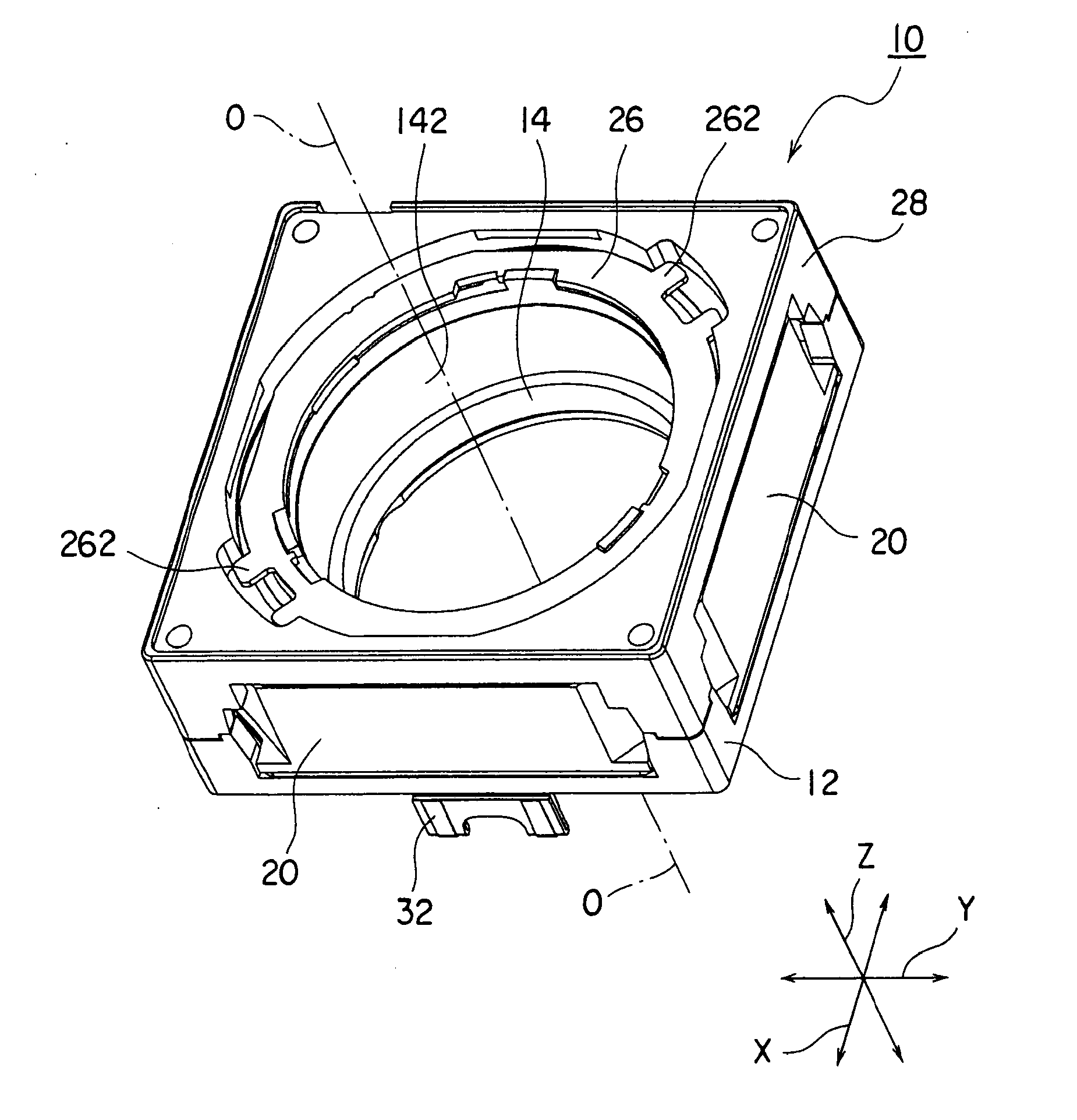
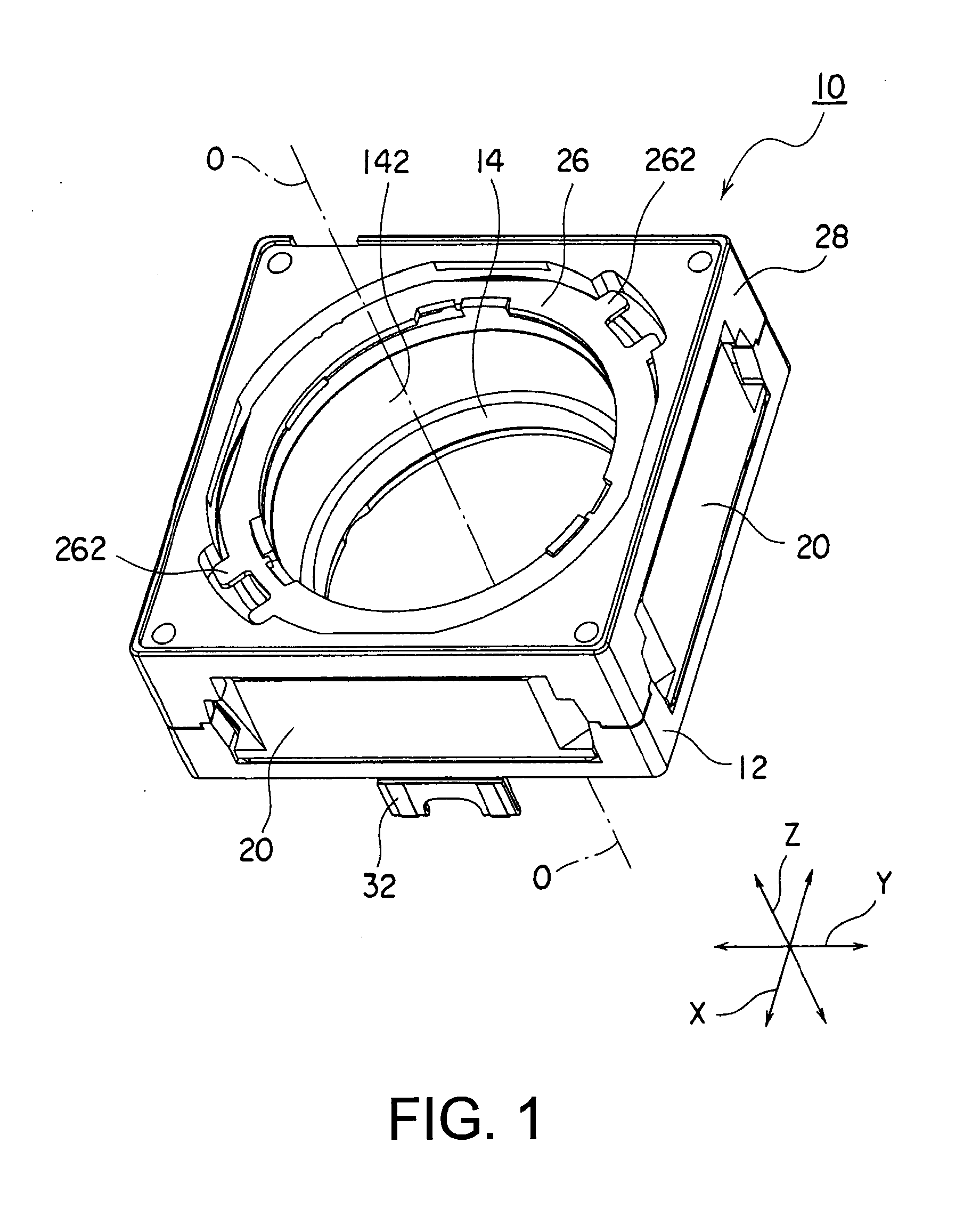
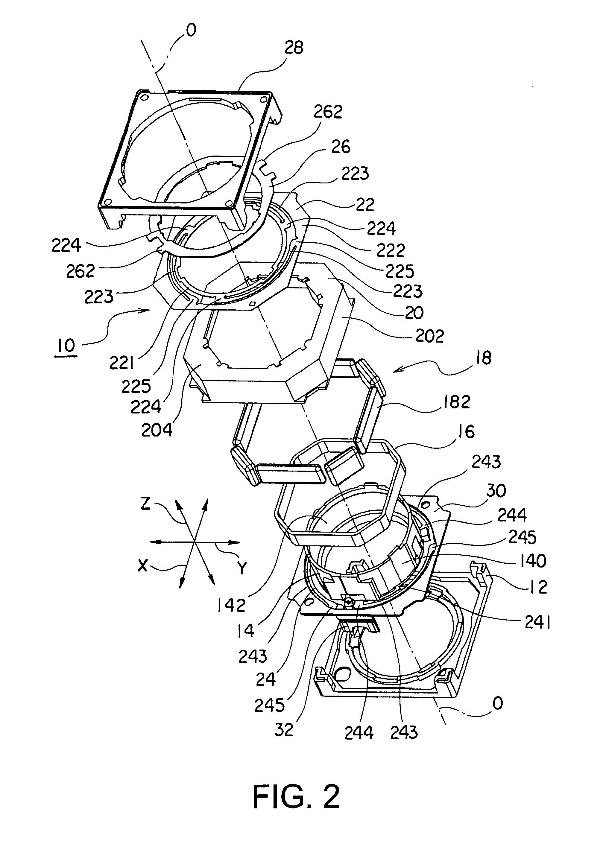
[0046]Referring to FIGS. 1 and 2, the description will proceed to a lens driving device 10 according to a first exemplary embodiment of this invention. FIG. 1 is a perspective view of the lens driving device 10. FIG. 2 is an exploded perspective view of the lens driving device 10.
[0047]Herein, in the manner shown in FIGS. 1 and 2, an orthogonal coordinate system (X, Y, Z) is used. In a state illustrated in FIGS. 1 and 2, in the orthogonal coordinate system (X, Y, X), an X-axis direction is a fore-and-aft direction (a depth direction), a Y-axis direction is a left-and-right direction (a width direction), and a Z-axis direction is an up-and-down direction (a height direction). In addition, in the example being illustrated in FIGS. 1 and 2, the up-and-down direction Z is a direction of an optical axis O of a lens.
[0048]However, in an actual use situation, the direction of the optical axis O, namely, the Z-axis direction becomes a fore-and-aft direction. In other words, an upper directi...
example 1
[0072]A first example of the present invention uses, as the material of the leaf springs (22, 24), high hardness non-magnetic stainless steel having high Vickers hardness by cold working that is less than 500 (HV) and which has low permeability. Such stainless steel can use, for example, NTK S-4 made in Nippon Metal Industry Co., Ltd (NIKKINKO). Chemical component (mass %) of the NTK S-4 is shown in as FIG. 3.
[0073]The high hardness non-magnetic stainless steel has relative magnetic permeability of about 1.002.
[0074]Although a row workpiece thereof has low Vickers hardness of 260 (HV), it is possible to rise the Vickers hardness up to 500 (HV) or more by applying cold working as shown in FIG. 4. In FIG. 4, a horizontal axis represents a rate (%) of the cold working while a vertical axis represents Vickers hardness (HV).
[0075]Now, the description will proceed to a method of manufacturing the row workpiece (thin plate) of the leaf spring by cold rolling. First, by using a row workpiec...
example 2
[0080]A second example of the present invention uses, as the material of the leaf springs (22, 24), high hardness stainless steel (austenitic chromium-nickel steel) having high Vickers hardness by cold working that is less than 500 (HV). Such stainless steel can use, for example, NTK 301 (SUS301) made in Nippon Metal Industry Co., Ltd (NIKKINKO). Chemical component (mass %) of the NTK 301 is shown in as FIG. 6.
[0081]The high hardness stainless steel has relative magnetic permeability of about 1.50.
[0082]Although a row workpiece thereof has low Vickers hardness of 191 (HV), it is possible to rise the Vickers hardness up to 500 (HV) or more by applying cold working as shown in FIG. 7. In FIG. 7, a horizontal axis represents a rate (%) of the cold working while a vertical axis represents Vickers hardness (HV).
[0083]Inasmuch as a method of manufacturing the row workpiece (thin plate) of the leaf spring by cold rolling is similar to that of the above-mentioned first embodiment, the descr...
PUM
 Abstract
Description
Claims
Application Information