Grain-oriented electrical steel sheet and manufacturing method thereof

a technology of electrical steel and grain orientation, which is applied in the direction of solid-state diffusion coating, coating, transportation and packaging, etc., can solve the problems of reducing the yield of grain-oriented electrical steel sheets, and reducing the cost of production. , to achieve the effect of suppressing defects of glass coating films, reducing cost and improving yield

Active Publication Date: 2011-09-01
NIPPON STEEL CORP
View PDF12 Cites 3 Cited by
  • Summary
  • Abstract
  • Description
  • Claims
  • Application Information

AI Technical Summary

Benefits of technology

[0015]According to the present invention, it is possible to effectively suppress defects of a glass coating film. A yield is thereby improved and a cost can be reduced. Besides, it is possible to stably manufacture grain-oriented electrical steel sheets.

Problems solved by technology

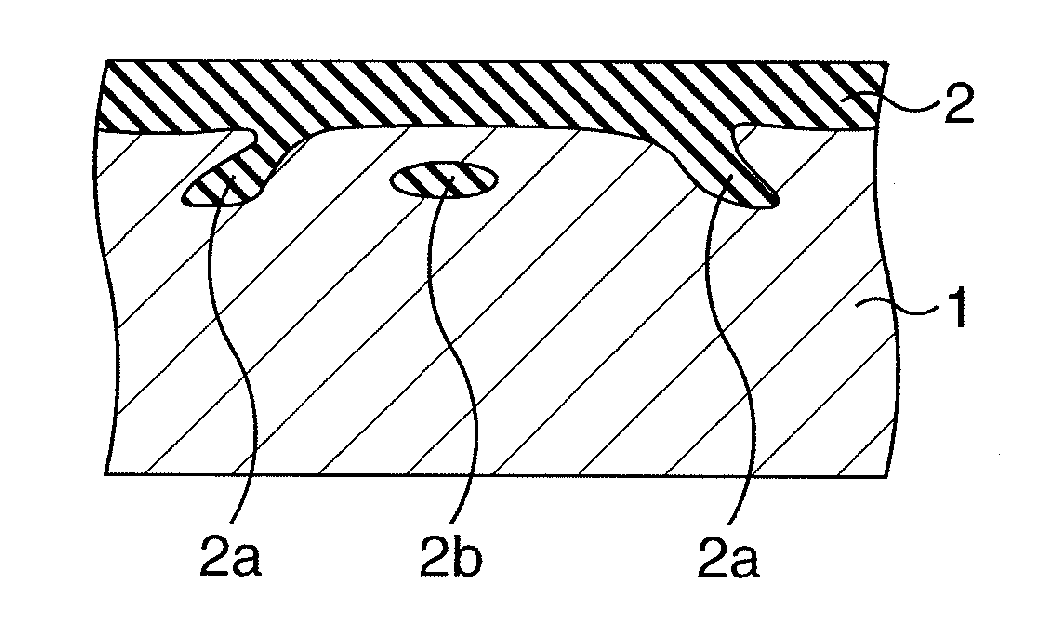
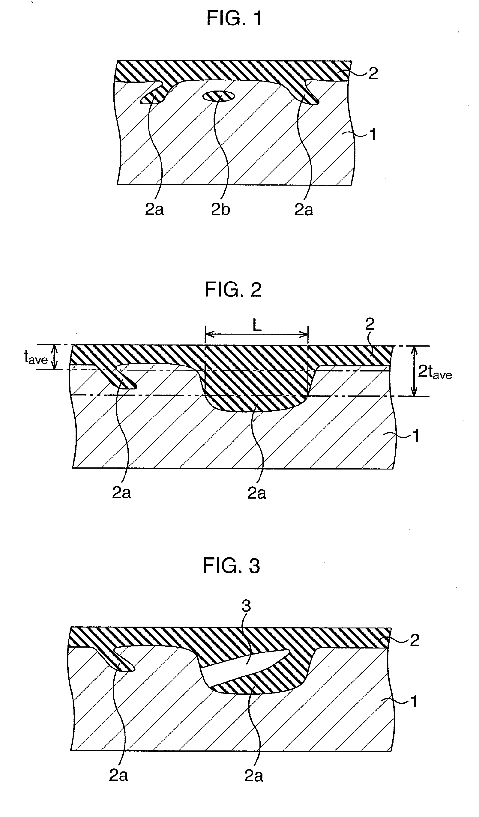
However, there is a case when a number of defects occur at the glass coating film in the conventional manufacturing method as stated above.
If the defect as stated above occurs, an external appearance deteriorates because the steel strip exposes from the glass coating film.
Besides, the defect of the glass coating film leads to the core loss and / or deterioration of the excitation properties.
A study to reduce the defects of the glass coating film has been made, but it is impossible to fully reduce the defects by the former technologies.

Method used


Image

  • Grain-oriented electrical steel sheet and manufacturing method thereof
  • Grain-oriented electrical steel sheet and manufacturing method thereof
  • Grain-oriented electrical steel sheet and manufacturing method thereof

Examples


example

Example 1

[0072]A slab containing C: 0.05 mass %, Si: 3.2 mass %, Mn: 0.09 mass %, P: 0.02 mass %, S: 0.006 mass %, Al: 0.026 mass %, N: 0.009 mass %, and Cr: 0.1 mass %, and the remaining portion was composed of Fe and inevitable impurities was manufactured. Subsequently, the slab heating (step S1), the hot rolling (step S2), the annealing (step S3) and the cold rolling (step S4) were performed in accordance with the flowchart illustrated in FIG. 8. The thickness of the steel strip after the cold rolling was set to be 0.23 mm. Next, the annealing (step S5) and the nitriding process (step S6) were performed, and the C content was set to be 0.001 mass %, and the N content was set to be 0.02 mass % in the steel strip. Subsequently, the coating and the drying of the annealing separating agent of which major constituent was MgO were performed, and thereafter, the switching temperatures to the H2 gas atmosphere were set as listed in table 2, to perform the finish annealing (step S7). In t...

example 2

[0075]A slab containing C: 0.05 mass %, Si: 3.2 mass %, Mn: 0.09 mass %, P: 0.02 mass %, S: 0.006 mass %, Al: 0.026 mass %, N: 0.009 mass %, and Cr: 0.1 mass %, and the remaining portion was composed of Fe and inevitable impurities was manufactured. Subsequently, the slab heating (step S1), the hot rolling (step S2), the annealing (step S3) and the cold rolling (step S4) were performed in accordance with the flowchart illustrated in FIG. 8. The thickness of the steel strip after the cold rolling was set to be 0.23 mm. Next, the annealing (step S5) and the nitriding process (step S6) were performed, and the C content was set to be 0.001 mass %, and the N content was set to be 0.02 mass % in the steel strip. Subsequently, the coating and the drying of the annealing separating agent of which major constituent was MgO were performed, and thereafter, the oxygen potentials (P (H2O) / P (H2)) in the heating were set as listed in table 3, and the finish annealing (step S7) was performed. In t...


PUM

PropertyMeasurementUnit
thicknessaaaaaaaaaa
temperatureaaaaaaaaaa

Abstract

Nitriding process of a steel strip is performed. Next, annealing is performed to form a forsterite based glass coating film at a surface of the steel strip. Heating is performed up to 1000° C. or more in a mixed gas atmosphere containing H2 gas and N2 gas, and a rate of N2 gas is 20 volume % or more, next, the atmosphere is switched into H2 gas atmosphere at the temperature of 1000° C. or more and 1100° C. or less, when the annealing is performed. An oxygen potential P (H2O)/P (H2) is set to be 0.05 to 0.3 when the temperature is 850° C. or less during the heating in the mixed gas atmosphere.

Description

TECHNICAL FIELD[0001]The present invention relates to a grain-oriented electrical steel sheet, and a manufacturing method thereof suitable for an iron core of electric equipments such as a voltage transformer and an electric transformer.BACKGROUND ART[0002]In a conventional manufacturing method of a grain-oriented electrical steel sheet, an insulating film called as a glass coating film is formed at a surface of a steel strip at finish annealing, and a control of a crystal orientation using AlN precipitates as an inhibitor is performed. A tensile tension acts on the steel strip by the glass coating film, and thereby, a core loss of the grain-oriented electrical steel sheet is reduced. There is a case when the glass coating film is called as a forsterite film or a primary coating film. Besides, excitation properties improve owing to the control of the crystal orientation.[0003]However, there is a case when a number of defects occur at the glass coating film in the conventional manufa...

Claims


Application Information

Patent Timeline
Patent Type & Authority Applications(United States)
IPC IPC(8): C23C22/82B32B15/04B32B7/02
CPCC21D1/76C21D8/1283C22C38/001C22C38/004C22C38/02Y10T428/2495C22C38/06C22C38/34C23C8/24C23C8/26C23C8/80C22C38/04
Inventor NATORI, YOSHIAKIYAMAZAKI, SHUICHITAKAHASHI, FUMIAKITAKEBAYASHI, SEIKI
Owner NIPPON STEEL CORP
Why Eureka
Try Eureka