Contactless power reception circuit and contactless power tranmission system

a technology of contactless power and transmission circuit, which is applied in the direction of transformers, inductances, instruments, etc., can solve the problems of signal waveform deformation and interference with load modulation communication, and achieve the effects of reducing transmission rate, compact size, and suppressing communication error

Inactive Publication Date: 2011-09-01
MURATA MFG CO LTD
View PDF5 Cites 39 Cited by
  • Summary
  • Abstract
  • Description
  • Claims
  • Application Information

AI Technical Summary

Benefits of technology

[0006]The present disclosure provides a contactless power reception circuit and a contactless power transmission system that can ...

Problems solved by technology

If a backflow prevention device is not provided, a discharge from the input smoothing capacitor can cause sig...

Method used


Image

  • Contactless power reception circuit and contactless power tranmission system
  • Contactless power reception circuit and contactless power tranmission system
  • Contactless power reception circuit and contactless power tranmission system

Examples


Embodiment Construction

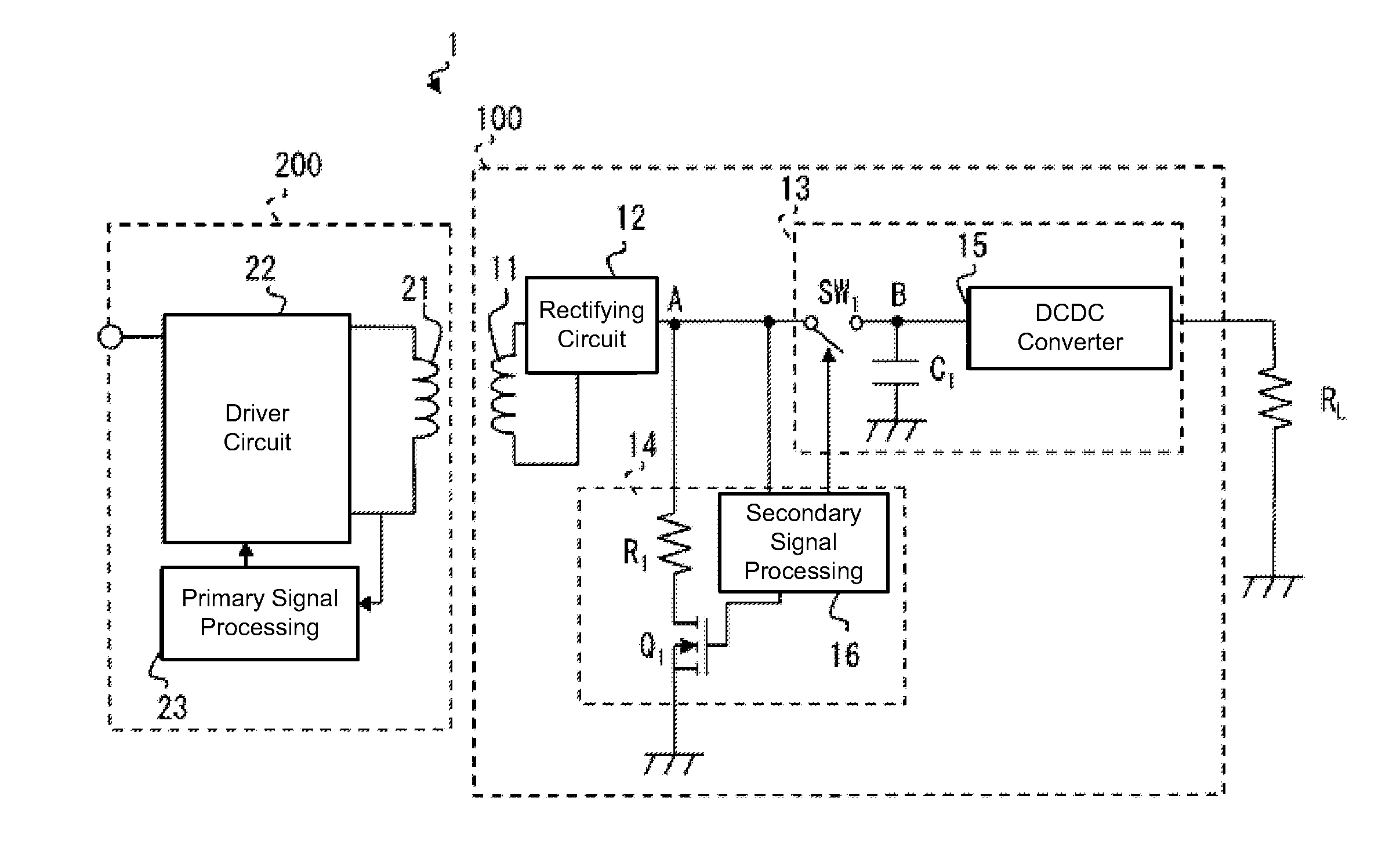
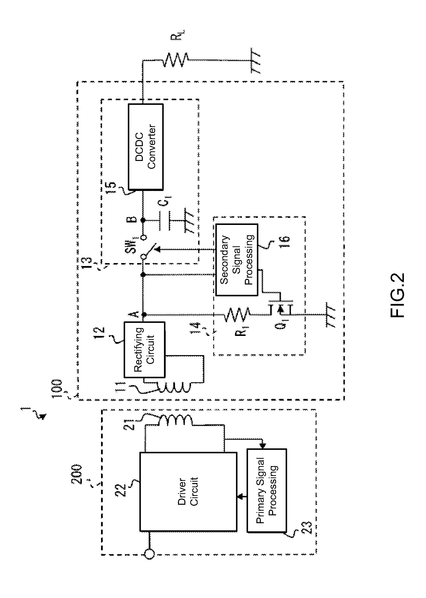
[0027]The inventors have realized that when a load modulation communication is conducted with a capacitor having a large capacitance such as in a range of several tens to several hundreds ofμF, the capacitor discharges at every load modulation and the waveform of the voltage signal is deformed, which subsequently causes problems such as a communication error and a decreased transmission rate.

[0028]To suppress the waveform deformation of the voltage signals, decreasing a time constant by decreasing resistance of the load modulation has been considered. In that case, however, a current running through the load modulation resistor can become large, resulting in large power consumption. Decreasing the time constant by disposing the load modulation resistors in parallel is also considered, but that can cause enlargement of the size and an increase in cost.

[0029]Further, when a contactless power supply is used for quick recharging a laptop computer or other mobile equipment, for example, ...


PUM


Abstract

This disclosure provides a contactless power reception circuit that includes a power reception part, a voltage rectifying part, a voltage transforming part and a load modulation part. The voltage transforming part includes a smoothing capacitor, a DCDC converter and a backflow prevention device. The power reception part is couplable with an electromagnetic field adjacent to the contactless power reception circuit. The rectifying part rectifies a voltage output from the power reception part, the voltage transforming part transforms rectified voltage from the rectifying part, and the load modulation circuit conducts a load modulation while signals are transmitted. The smoothing capacitor smoothes a voltage input to the voltage transforming part, the DCDC converter transforms voltage smoothed by the smoothing capacitor, and the backflow prevention device prevents backflow of charge from the smoothing capacitor while the signals are transmitted to a contactless power transmission circuit.

Description

CROSS REFERENCE TO RELATED APPLICATIONS[0001]The present application is a continuation of International Application No. PCT / JP2009 / 059337, filed May 21, 2009, which claims priority to Japanese Patent Application No. 2008-250922 filed Sep. 29, 2008, the entire contents of each of these applications being incorporated herein by reference in their entirety.TECHNICAL FIELD[0002]The present invention relates to a contactless power reception circuit which receives a power supply by coupling with an adjacent electromagnetic field and a contactless power transmission system including the contactless power reception circuit and a contactless power transmission circuit which generates the adjacent electromagnetic field.BACKGROUND ART[0003]In a RFID using a contactless power supply, a contactless power reception circuit is provided in a wireless tag side. The contactless power reception circuit receives power from an adjacent electromagnetic field of a reader-writer for example, by coupling, a...

Claims


Application Information

Patent Timeline
IPC IPC(8): H01F38/14G06K19/07
CPCH02J5/005H02J50/80H02J50/10
Inventor SHINODA, SATOSHISANO, TAKAHIDE
Owner MURATA MFG CO LTD
Why Eureka
Try Eureka