Method and apparatus for controlling the brightness of an LCD backlight

a technology of backlight and brightness, applied in the direction of instruments, static indicating devices, etc., can solve the problems of motion artefacts and undesirable effects of electro magnetic interference (emi) on the display, and achieve the effects of reducing electromagnetic interference, reducing motion artefacts, and improving picture quality

Inactive Publication Date: 2011-09-01
ITI SCOTLAND
View PDF4 Cites 8 Cited by
  • Summary
  • Abstract
  • Description
  • Claims
  • Application Information

AI Technical Summary

Benefits of technology

[0014]In this way, a spatial variation in the LED drive is provided. The intermodulation of the video signal and the drive signal for the display is further reduced, improving picture quality, reducing motion artefacts, patterning and flicker. Further, the spatial variation reduces electromagnetic interference with other parts of the display for example the liquid crystal drive signals as well as reducing electromagnetic inference with other equipment. Further, the implementation can be simplified using reduced components and hence reducing requirements to screen the LED backlight wiring (circuit board tracking).
[0015]The time interval may be determined to ensure no visible LED flicker and may be variable. The calculated number of LEDs may be selected according to a recorded or synthesised incoherent sequence to form the spatial distribution pattern, for example, the spatial distribution pat

Problems solved by technology

This results in motion artefacts, flicker and moving or static patterning and E

Method used


Image

  • Method and apparatus for controlling the brightness of an LCD backlight
  • Method and apparatus for controlling the brightness of an LCD backlight
  • Method and apparatus for controlling the brightness of an LCD backlight

Examples


Embodiment Construction

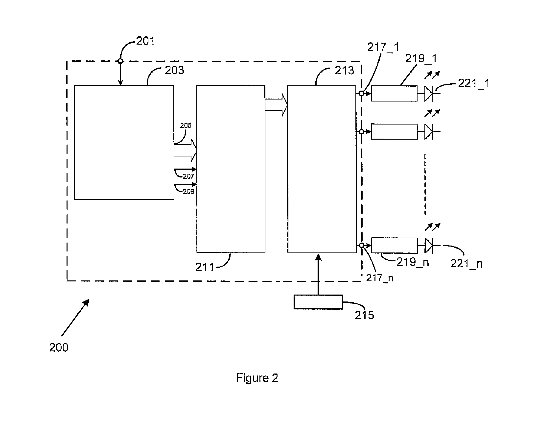
[0023]An embodiment of the present invention will now be described with reference to FIGS. 2 and 3.

[0024]The apparatus 200 comprises an input terminal 201 connected to an input of a microprocessor 203. The microprocessor 203 may be a microprocessor that controls the rest of the display unit that the backlight unit forms part of (not shown here) or it may be dedicated to the functions described below with reference to FIG. 3.

[0025]The microprocessor 203 comprises an address output port 205, a SET output 207 and a CLEAR_ALL output 209. The address output port 205, the SET output 207 and the CLEAR_ALL output 209 of the microprocessor 203 are connected to respective inputs of a NEXT_LED_MAP register 211. The output port of the NEXT_LED_MAP register 211 is connected to the respective input of a CURRENT_LED_MAP register 213. The CURRENT_LED_MAP register 213 is also connected to a backlight clock 215. The NEXT_LED_MAP register 211 and the CURRENT_LED_MAP register 213 comprise a plurality o...


PUM


Abstract

The brightness of a LCD backlight, comprising a plurality of LEDs or LED chains (2211 to 221n), is controlled by a processor (203) for calculating the number of LEDs of a plurality of LEDs to be illuminated for a determined brightness and selecting the calculated number of LEDs or LED chains to form a spatial distribution pattern; and drivers (2191 to 219n) for illuminating the calculated number of LEDs in a random or pseudo-random sequence.

Description

FIELD OF THE INVENTION[0001]The present invention relates to method and apparatus for controlling the brightness of a LCD backlight. In particular, it relates to controlling the brightness of an LED backlight for a LCD.BACKGROUND OF THE INVENTION[0002]Many techniques have been developed to control the brightness of an LED backlight in a LCD. Some LED backlights use white LEDs while others use a combination of coloured LEDs to produce the required white light. In the latter case, the resultant colour is very dependant on the relative brightness of the LEDs and the relationship between the forward current of a LED and its brightness which is not precisely linear. The precise colour of a white LED can also change with its forward current. For this reason the brightness of LED backlights is normally controlled by pulsing the LED on and off at a single current and adjusting the proportion of the time that they are switched on. The pulse rate is chosen so that the response of the human ey...

Claims


Application Information

Patent Timeline
IPC IPC(8): G09G3/36
CPCG09G3/3426G09G2330/06G09G2320/064G09G2320/0247G09G3/3406G09G3/36
Inventor JENKINS, KEITH NOELWORDSWORTH, GARY BRYAN
Owner ITI SCOTLAND
Why Eureka
Try Eureka