Electrostatic lens structure

Active Publication Date: 2011-09-08
ASML NETHERLANDS BV
View PDF8 Cites 37 Cited by
  • Summary
  • Abstract
  • Description
  • Claims
  • Application Information

AI Technical Summary

Benefits of technology

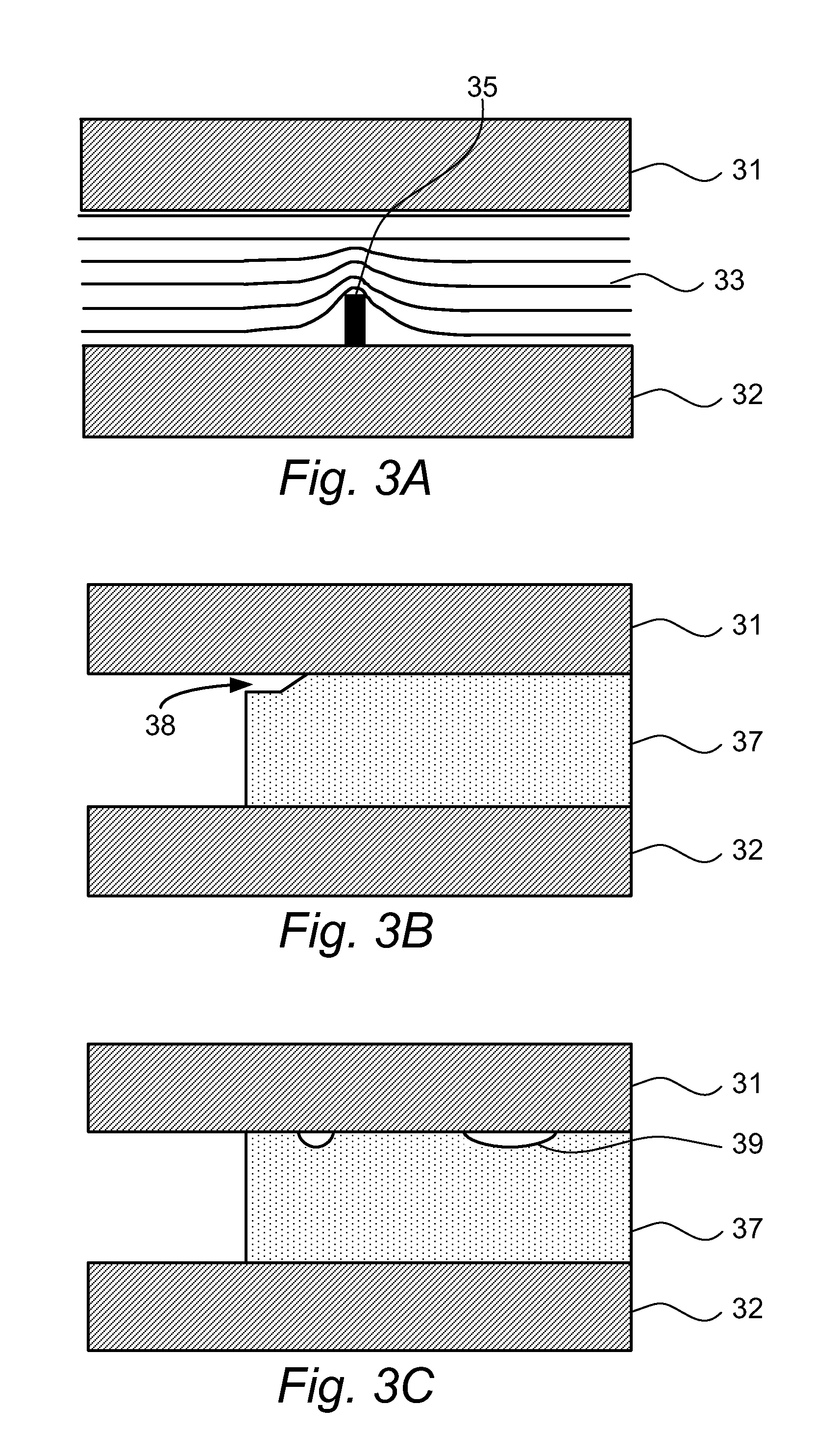
[0011]It has also been recognized that electric field enhancement plays a role in causing flashover and recognition of this leads to better methods for preventing flashover. Any enhancement of the electric field should be avoided or reduced, particularly at the negative electrode. Voids between a portion of the insulating structure and one of the conductive plates cause an enhancement or elevation of the electric field locally in the void. The smaller the width of the void in comparison to the distance between the plates, the greater will be any enhancement of the electric field in the void. Such an electric field enhancement makes the location of the void more susceptible to flashover. When such a void occurs at a so-called triple points, i.e. a point at which there is a boundary between air/vacuum, conductor and insulator, the likelihood of an electrical d

Problems solved by technology

Such voids at triple points may occur in practice due to chipping or cracking at the edge of the insulator or as a result of manuf

Method used


Image

  • Electrostatic lens structure
  • Electrostatic lens structure
  • Electrostatic lens structure

Examples


Embodiment Construction

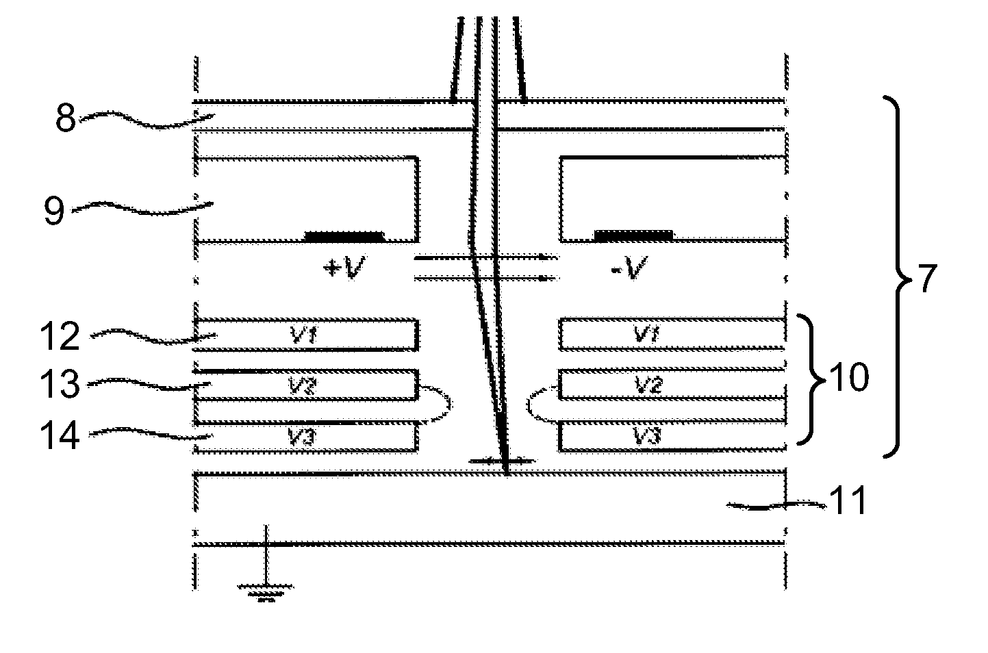
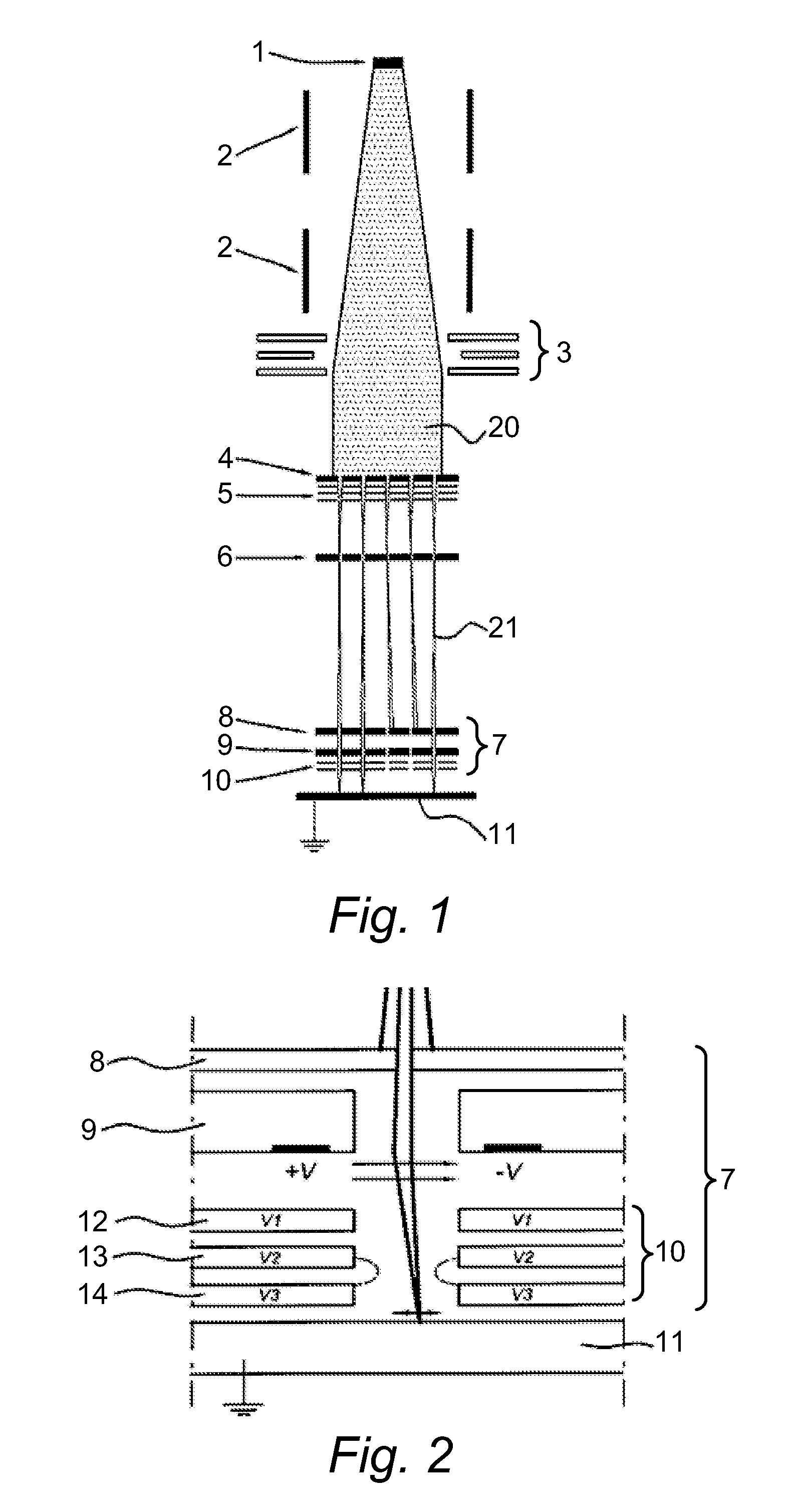
[0034]The following is a description of a number of embodiments of the invention, given by way of example only and with reference to the drawings. FIG. 1 schematically shows a simplified schematic drawing of an example of a charged particle multi-beamlet lithography system based upon an electron beam optical system without a common cross-over of all the electron beamlets. Such lithography systems are described for example in U.S. Pat. Nos. 6,897,458, 6,958,804, 7,084,414, and 7,129,502, which are all hereby incorporated by reference in their entirety, assigned to the owner if the present invention.

[0035]The lithography system comprises an electron source 1 for producing a homogeneous, expanding electron beam 20. Beam energy is preferably maintained relatively low in the range of about 1 to 10 keV. To achieve this, the acceleration voltage is preferably low, the electron source preferably kept at between about −1 to −10 kV with respect to the target at ground potential, although othe...


PUM


Abstract

An electrostatic lens comprising a first conductive plate with a first aperture, a second conductive plate with a second aperture, the second aperture being substantially aligned with the first aperture, a voltage supply for supplying a first voltage to the first conductive plate and a second voltage to the second conductive plate, the first voltage being lower than the second voltage, and an insulating structure for separating the first conductive plate from the second conductive plate. The insulating structure comprises a first portion in contact with the first conductive plate and a second portion in contact with the second conductive plate, the first portion having an overhanging portion and the second portion having an indented portion at an edge of the insulating structure, so that a gap is formed between the overhanging portion and the second conductive plate.

Description

BACKGROUND OF THE INVENTION[0001]1. Field of the Invention[0002]The invention relates to an electrostatic lens or an electrostatic lens array. Furthermore, the invention relates to a charged particle lithography system comprising such an electrostatic lens or electrostatic lens array. Additionally, the invention relates to a method of manufacturing an insulating structure for use in an electrostatic lens.[0003]2. Description of the Related Art[0004]Electrostatic lenses are used in charged particle beam columns for use in applications like scanning electron microscopes and lithography apparatus. An electrostatic lens typically consists of conductive plates, generally silicon plates provided with a conductive layer, stacked in a direction of the charged particle beam. The conductive plates may be separated by electrically isolating spacers, e.g. made of glass or other suitable insulating materials. The plates and spacers have aligned apertures enabling a charged particle beam to pass ...

Claims


Application Information

Patent Timeline
IPC IPC(8): G03B27/54H01J3/14B23P17/04
CPCB82Y10/00B82Y40/00H01J37/12H01J37/3174Y10T29/49H01J2237/004H01J2237/0203H01J2237/03H01J2237/04924H01J37/3177
Inventor STEENBRINK, STIJN WILLEMKONING, JOHAN JOOSTVELTMAN, PETER
Owner ASML NETHERLANDS BV
Why Eureka
Try Eureka