Head for thermal assisted magnetic recording device, and thermal assisted magnetic recording device

a recording device and magnetic recording technology, applied in the field of optical nearfield generator and recording and reproducing apparatus, can solve the problems of semiconductor laser considerably rising, semiconductor laser is less easily dissipated, slider floating stability increasing, etc., to achieve the effect of increasing the total height of the head, increasing the floating stability of the slider, and reducing the thickness of the driv

Active Publication Date: 2011-09-08
HITACHI LTD
View PDF10 Cites 80 Cited by
  • Summary
  • Abstract
  • Description
  • Claims
  • Application Information

AI Technical Summary

Benefits of technology

[0040]According to the present invention, the semiconductor laser can be placed on the side surface of the floating slider, and hence it is not necessary to increase the total height of the head. Accordingly, the floating stability of the slider increases. In addition, it is not necessary to increase the interval between the disks in the drive, and hence the thickness of the drive can be kept small. In addition, light is directly introduced from the si...

Problems solved by technology

If the height becomes larger as described above, the floating of the slider becomes unstable, for example, when an impact is applied to a drive.
However, it is necessary to cause light to enter from the side surface of the waveguide, and hence the grating co...

Method used


Image

  • Head for thermal assisted magnetic recording device, and thermal assisted magnetic recording device
  • Head for thermal assisted magnetic recording device, and thermal assisted magnetic recording device
  • Head for thermal assisted magnetic recording device, and thermal assisted magnetic recording device

Examples


Embodiment Construction

[0079]Hereinafter, embodiments of the present invention are described with reference to the drawings.

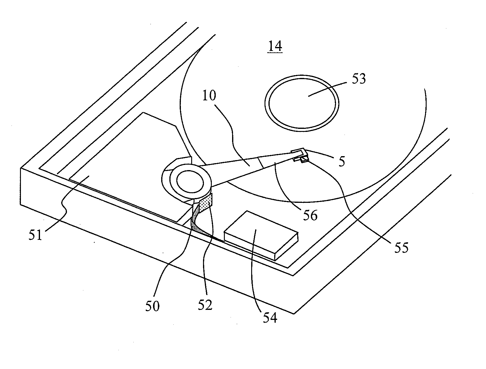
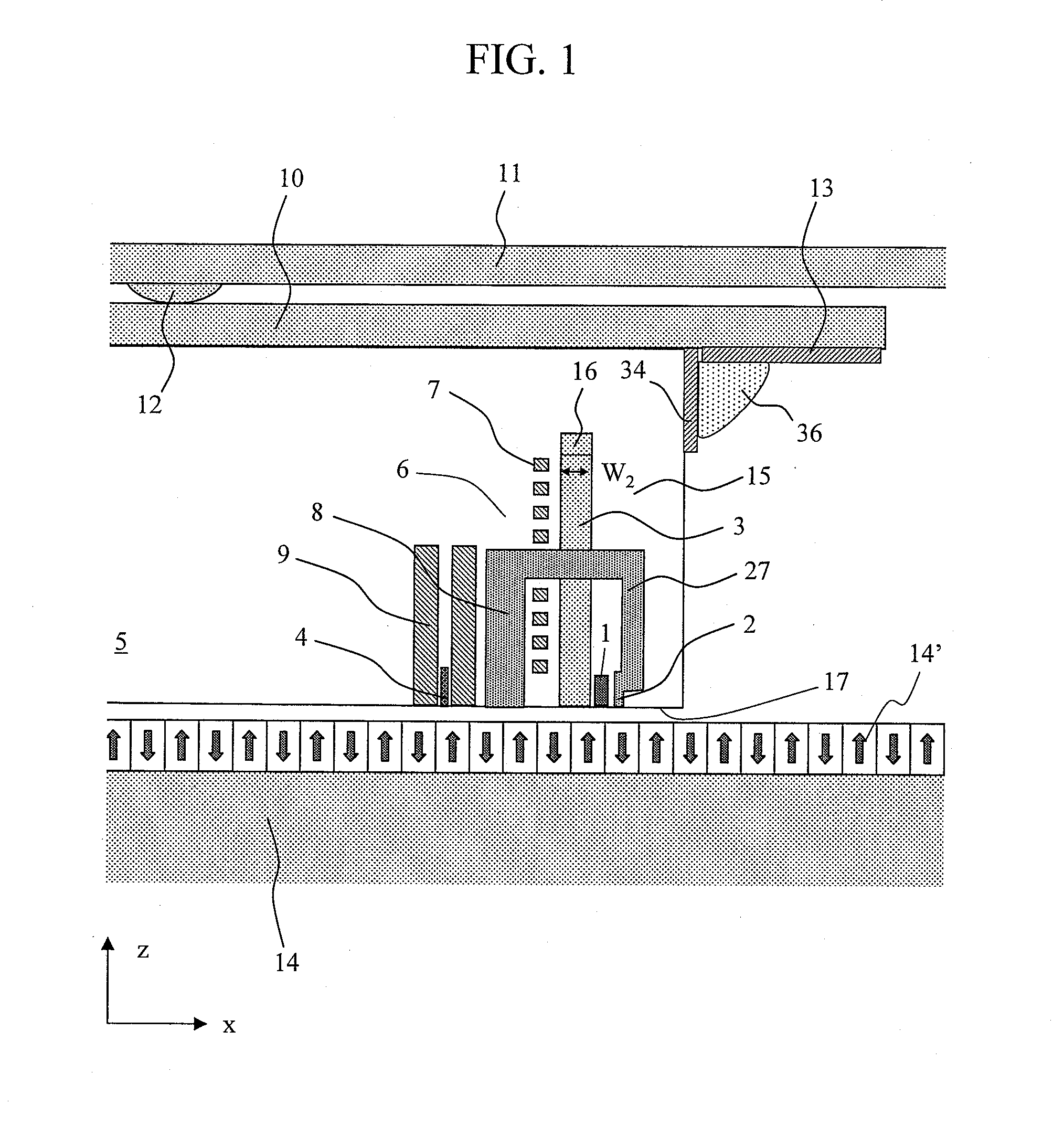
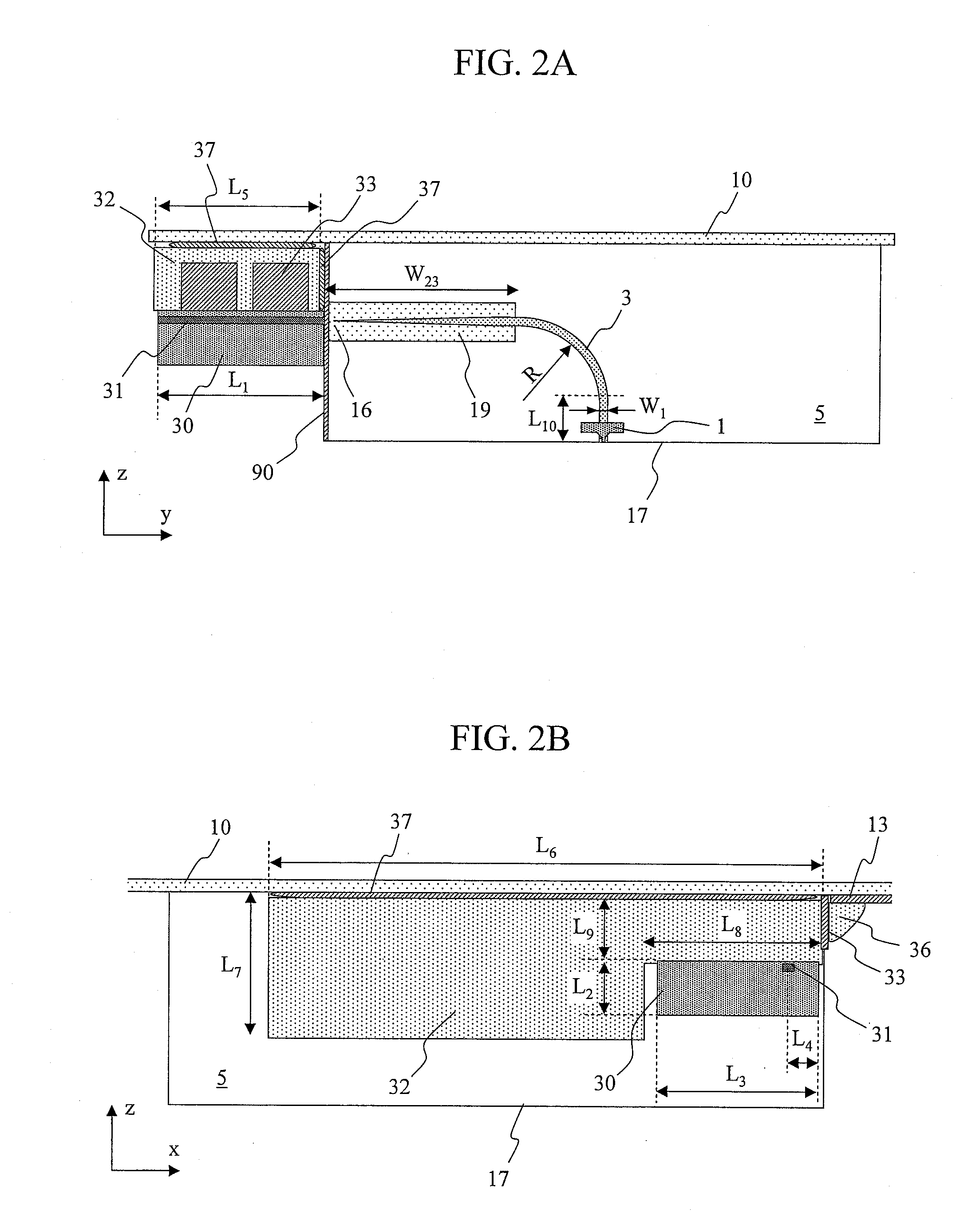
[0080]FIGS. 1 to 6 each illustrate a configuration example of a head for thermal assisted magnetic recording device according to the present invention. As illustrated in FIG. 1, a magnetic field for recording is generated by a coil 7 and a magnetic head part 6, and the magnetic head part 6 includes a thick magnetic pole 27 for transmitting a magnetic flux generated by the coil 7, a main pole 2, and a return pole 8. The magnetic field generated by the coil 7 is transmitted through the thick magnetic pole 27 to reach the main pole 2 placed in the vicinity of an optical near-field generating element 1. At the moment of recording, a magnetic recording medium 14 is heated by an optical near-field generated by the optical near-field generating element 1, and at the same time, a magnetic field for recording generated by the main pole 2 is applied to the magnetic recording medium 14, whereby...


PUM


Abstract

In a head for thermal assisted magnetic recording device, a semiconductor laser is mounted so that the total height of the head does not become larger and light power fluctuation due to wavelength fluctuation occurs less frequently. In addition, the rise in temperature of the mounted semiconductor laser is suppressed. A semiconductor laser is placed on a side surface which is different from surfaces on an inflow end side and a trailing side, of four side surfaces of a floating slider. An entrance of a waveguide is placed on the side surface of the floating slider, to thereby cause emitted light from the semiconductor laser to directly enter the waveguide. A curved line part or a reflective mirror is formed in the middle of the waveguide so that the light which has entered the waveguide travels toward an optical near-field generating element.

Description

CLAIM OF PRIORITY[0001]The present application claims priority from Japanese patent application JP 2010-049511 filed on Mar. 5, 2010, the content of which is hereby incorporated by reference into this application.BACKGROUND OF THE INVENTION[0002]1. Field of the Invention[0003]The present invention relates to an optical near-field generator and a recording and reproducing apparatus using the same.[0004]2. Background Art[0005]In recent years, a thermally assisted magnetic recording system has been proposed as a recording system which realizes a recording density equal to or larger than 1 Tb / in2 (H. Saga, H. Nemoto, H. Sukeda, and M. Takahashi, Jpn. J. Appl. Phys. 38, Part 1, 1839 (1999)). In a conventional magnetic recording apparatus, when a recording density thereof is equal to or larger than 1 Tb / in2, loss of recorded information due to thermal fluctuation becomes a problem. In order to prevent this problem, it is necessary to increase a coercive force of a magnetic recording mediu...

Claims


Application Information

Patent Timeline
IPC IPC(8): G11B13/08
CPCG11B5/105G11B2005/0021G11B5/6088G11B5/314G11B5/1278
Inventor MATSUMOTO, TAKUYA
Owner HITACHI LTD
Why Eureka
Try Eureka