Two-cycle combustion engine

a combustion engine and two-cycle technology, applied in the direction of engine components, mechanical equipment, fuel injection apparatus, etc., can solve the problems of insufficient time available within the cycle for this purpose, increased hydrocarbon emissions, and scavenging losses, so as to achieve effective prevention of combustion in the nozzle area, increase gas flow, and fuel concentration increase

Inactive Publication Date: 2011-09-15
GANGLMAYR JOSEF
View PDF16 Cites 6 Cited by
  • Summary
  • Abstract
  • Description
  • Claims
  • Application Information

AI Technical Summary

Benefits of technology

[0004]The invention is therefore based on the object of providing a two-cycle combustion engine of the kind mentioned above in such a way that an advantageous mixture formation is obtained both in idling operation and in the lower part-load range as well as the full-load range, in combination with a reduction of the scavenging losses and the hydrocarbon emissions.
[0006]As a result of the alignment of the nozzle axes relative to the outflow direction of the respectively opposite transfer port, it is possible to utilize the respectively largest relative speed for fuel preparation as a result of the oppositely directed speed components between the fuel stream injected in the direction of the nozzle axis and the air flowing in from the respectively opposite transfer port, which leads to an advantageous mixture distribution in the combustion chamber in cooperation with the arrangement symmetry when using both injection nozzles and thus in the range of higher partial loads and in full-load operation. The point of intersection of the nozzle axes on the side of the cylinder axis facing away from the exhaust port displaces the fanning of the injected fuel jets which is relevant for mixture preparation with the help of the air injected in the opposite direction relative to the fuel via the transfer ports, so that scavenging losses can be prevented to a substantial extent. It needs to be considered in this connection that the fuel jets and the oppositely directed air flows will meet one another above the piston crown, leading to a flow of the forming mixture directed away from the piston crown towards the cylinder head and preventing a wetting of the piston crown with fuel which would lead to hydrocarbon emissions.
[0007]If only one injection nozzle is used for idling operation and the lower part-load range, the fuel is injected through this injection nozzle not into the combustion chamber above the piston crown but in the known manner (AT 503 127 B1) through a casing opening of the piston into the crankcase on the circumferential side facing the injection nozzle. As a result of the flow motion in the crankcase and on the bottom side of the piston there will be a substantially even distribution of the injected fuel and, as a result, there will be an even introduction of the fuel / air mixture through the transfer ports into the combustion chamber of the cylinder. A symmetric distribution of fuel is thus ensured in the combustion chamber both in idling operation and in the lower part-load range.
[0009]In order to achieve advantageous pressure conditions in the cylinder for the injection of the fuel, the nozzle axes of the injection nozzles can intersect the inside surfaces of the cylinder with respect to height between the timing edges of the transfer ports and the exhaust port. The injection nozzle is therefore only loaded with the low pressures at the end of the expansion phase. Moreover, the temperature is kept at a low level by the incoming fresh air, so that coking in the nozzle area can be effectively prevented. The height position of the injection nozzles relating to the timing edges of the transfer ports and the exhaust port also allows angles of inclination for the nozzle axes which are advantageous for the mixture preparation in the combustion chamber and, depending on this, the outflow sections of the transfer ports.
[0010]If at least one of the transfer ports originates from an intake opening provided in the cylinder which is opposite to a casing opening of the piston in the stroke position of the piston for the opened transfer port, an increased gas flow is obtained within the piston with the effect that no higher fuel concentration can build up in the piston area, so that all disadvantages caused by fuel enrichment in the piston area are avoided.

Problems solved by technology

Moreover, the two fuel jets have a considerable flow component in the direction towards the exhaust port after meeting one another in the region of the cylinder axis and the resulting fanning out of the fuel stream, leading to scavenging losses on the one hand and to increased hydrocarbon emissions on the other hand, because the air entering the combustion chamber from the crankcase via the transfer ports transversely to the direction of the fuel stream is unable to prevent the wetting of the piston crown with fuel which will flow off over the piston crown against the cylinder walls.
It has been noticed however that the time available within the cycles for this purpose is insufficient and therefore the disadvantages prevail concerning the piston and cylinder wall surfaces wetted with fuel, especially concerning the hydrocarbon emissions.

Method used


Image

  • Two-cycle combustion engine
  • Two-cycle combustion engine
  • Two-cycle combustion engine

Examples


Embodiment Construction

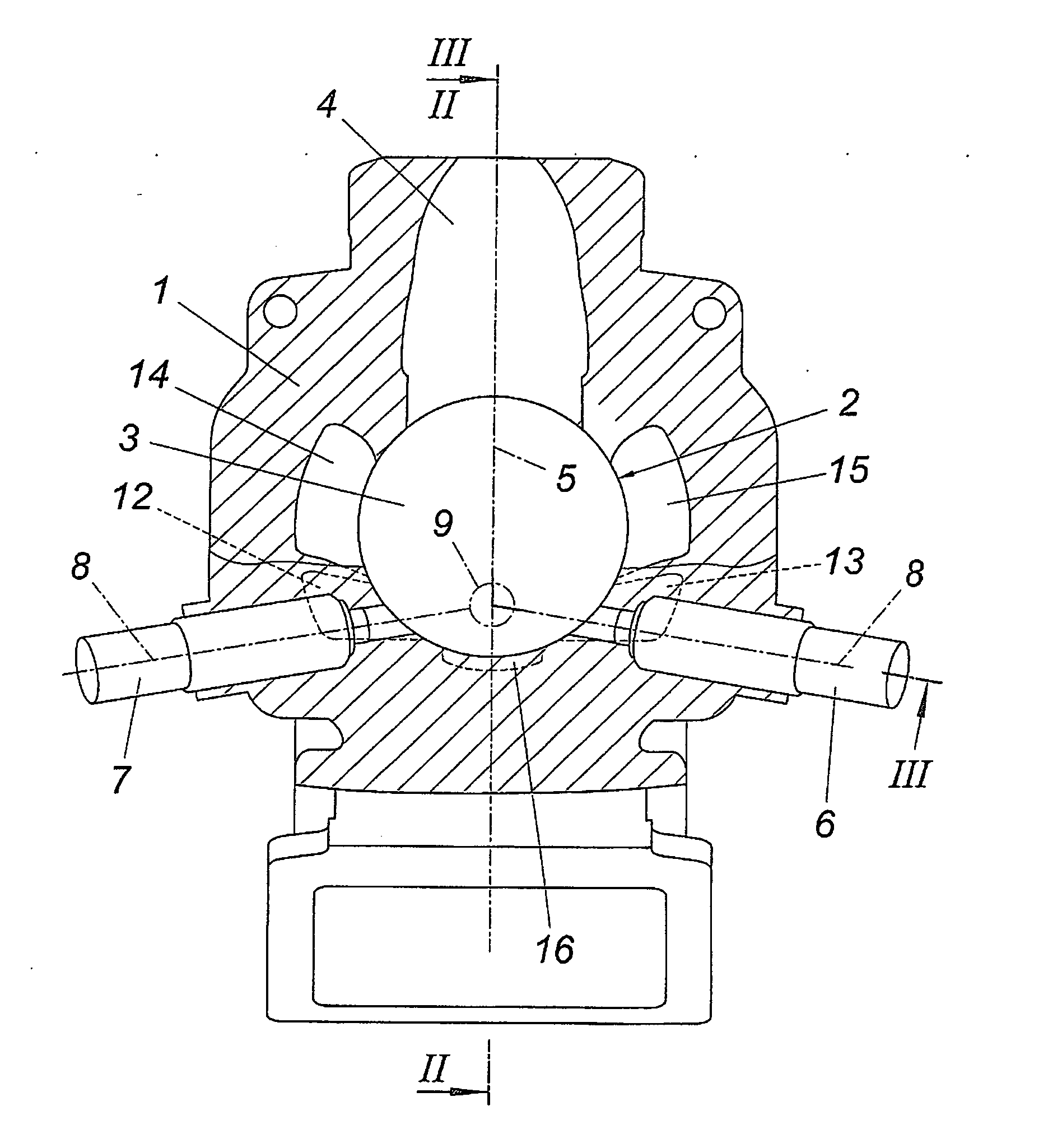
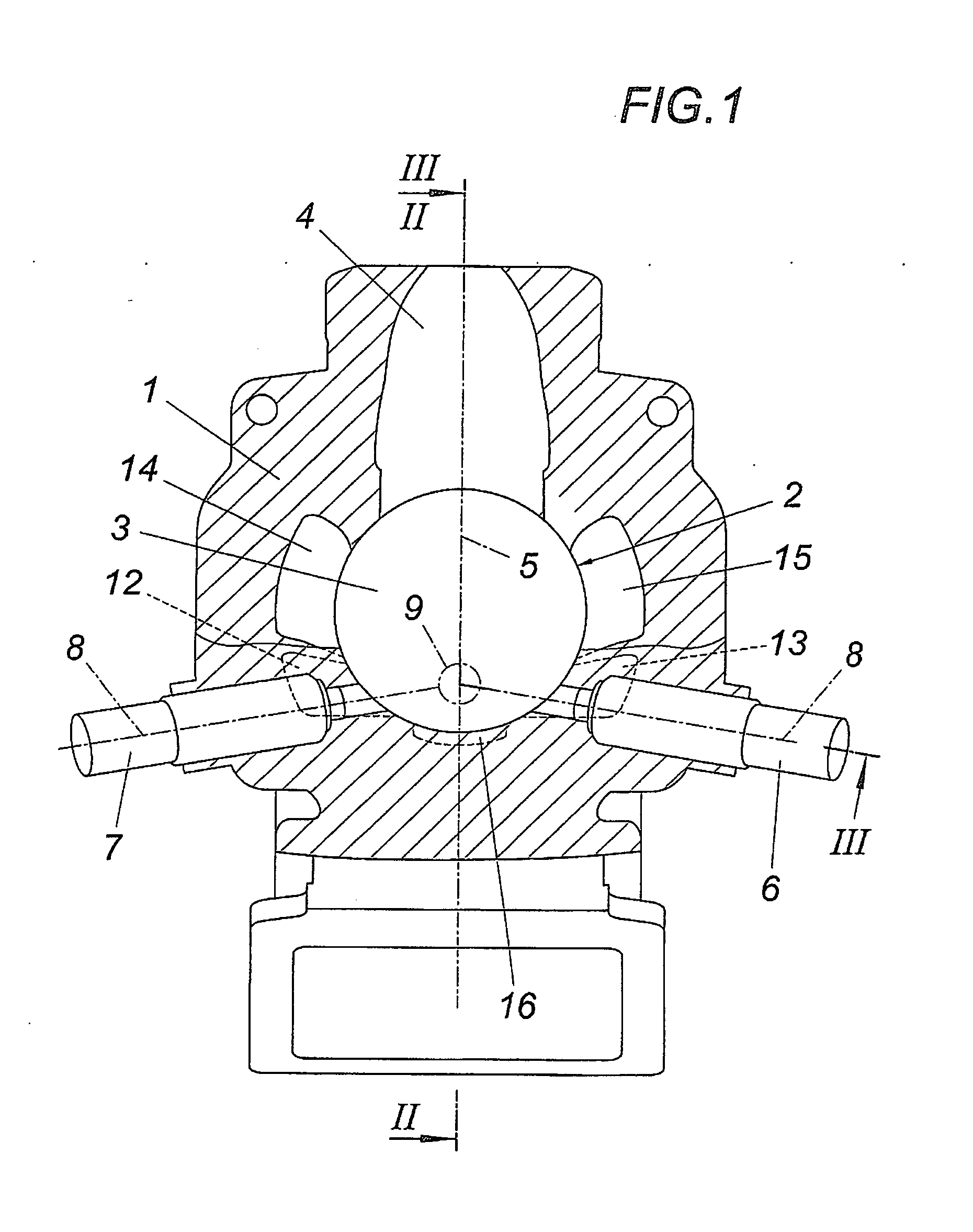
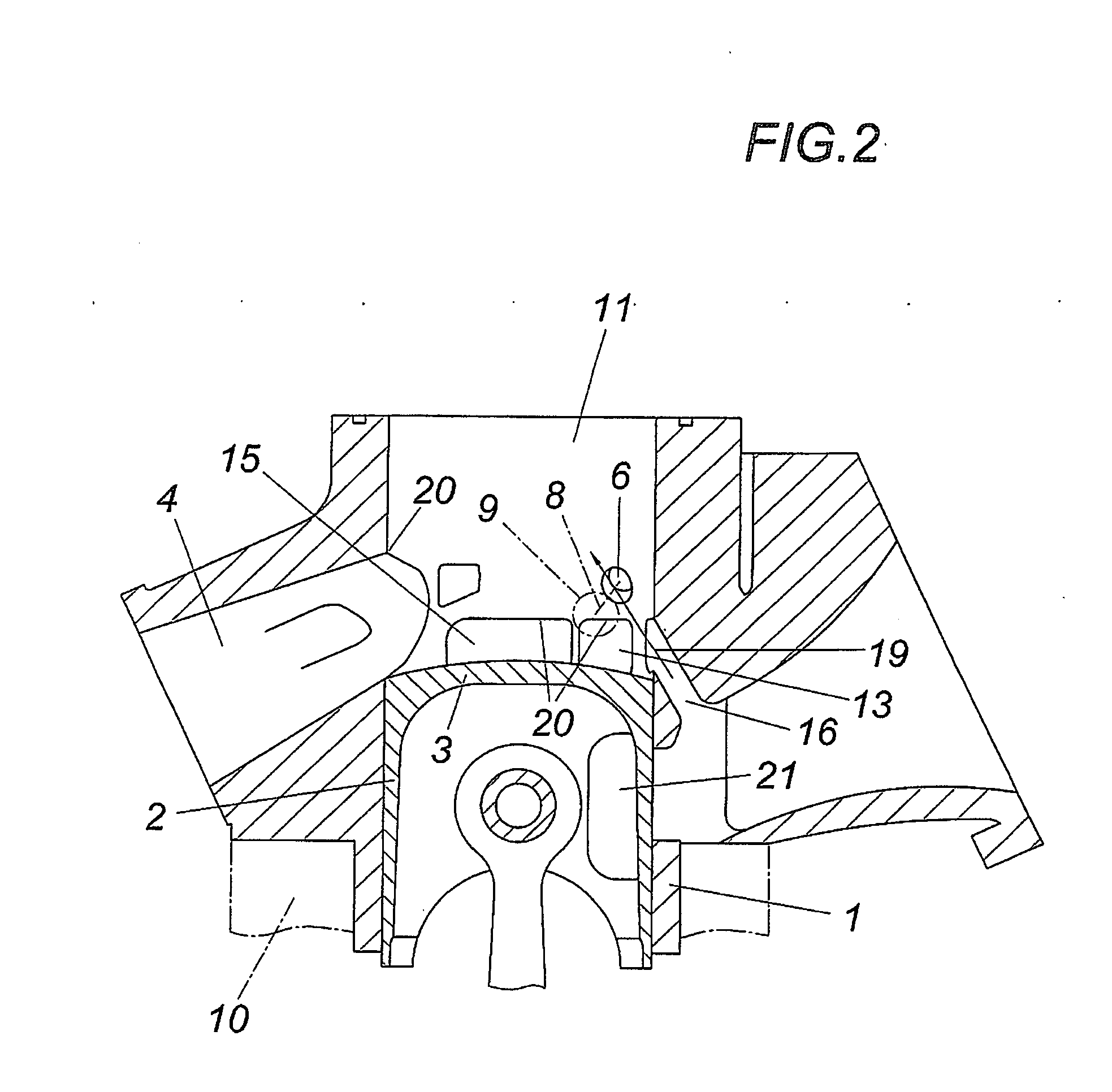
[0017]The drawing merely shows a cylinder 1 without cylinder head of a motor block of a two-cycle combustion engine. The piston shown in the bottom dead centre position is designated with reference numeral 2 and comprises a piston crown 3. On the side of the cylinder which is opposite of the exhaust port 4, two injection nozzles 6, 7 are provided symmetrically relative to a diametral plane 5 determined by the axis of the exhaust port 4, the nozzle axes 8 of which intersect in the diametral plane 5, namely in an intersecting point 9, which lies in the bottom dead centre position of piston 2 above the piston crown 3, as is shown especially in FIG. 5.

[0018]Transfer ports 12, 13 and 14, 15 are provided between the crankcase 10 and the combustion chamber 11 of the cylinder 1, which ports are opposite of one another in pairs and are arranged symmetrically in relation to the diametral plane 5. In addition, the cylinder 1 comprises a transfer port as a raising port 16 which is diametrically...


PUM


Abstract

The invention relates to a two-cycle combustion engine, comprising at least one cylinder (1) accommodating a piston (2) and provided with a cylinder head, a crankcase (10) which is in fluid connection with the cylinder (1) by way of transfer ports (12 to 16) which are disposed symmetrically opposite of one another with respect to a diametral plane (5) of the cylinder (1) that is determined by the axis of an exhaust port (4), and two injection nozzles (6, 7) for fuel disposed symmetrically with respect to said diametral plane (5), the nozzle axes (8) of which intersect one another above the piston crown (3) in the diametral plane (5) in the bottom dead centre position of the piston (2). In order to create advantageous scavenging conditions, it is proposed that the nozzle axes (8) intersect one another on the side of the cylinder axis facing away from the exhaust port (4) and extend at least approximately in the outflow direction (17) of the transfer ports (12, 13) respectively provided on the opposite side of the diametral plane (5), and the piston (2) comprises a casing opening (21) for injecting fuel into the crankcase (10) on at least one circumferential side facing the injection nozzles (6, 7).

Description

FIELD OF THE INVENTION[0001]The invention relates to a two-cycle combustion engine, comprising at least one cylinder accommodating a piston and provided with a cylinder head, a crankcase which is in fluid connection with a cylinder by way of transfer ports which are disposed symmetrically opposite of one another with respect to a diametral plane of the cylinder that is determined by the axis of an exhaust port, and two injection nozzles for fuel disposed symmetrically with respect to said diametral plane, the nozzle axes of which intersect one another above the piston crown in the diametral plane in the bottom dead centre position of the piston.DESCRIPTION OF THE PRIOR ART[0002]Since conventional injection nozzles can provide fuel only in a limited quantity range per injection cycle, it is known especially for powerful two-cycle combustion engines (EP 0 302 045 A2, EP 0 591 509 B1) to provide two injection nozzles, so that during a low demand for fuel in idling operation and in the ...

Claims


Application Information

Patent Timeline
Patent Type & Authority Applications(United States)
IPC IPC(8): F02M61/14
CPCF02B23/104F02B25/18F02B2075/025Y02T10/125F02F3/00F02F3/24F02F1/22Y02T10/12
Inventor GANGLMAYR, JOSEF
Owner GANGLMAYR JOSEF
Why Eureka
Try Eureka