Combustor and gas turbine having the same

a gas turbine and combustor technology, applied in the direction of instruments, heat measurement, lighting and heating apparatus, etc., can solve the problems of gas turbine combustion oscillations, space limitations in the casing during installation, etc., to reduce the space needed outside the combustor, reduce manufacturing costs, and facilitate extraction

Active Publication Date: 2011-09-15
MITSUBISHI POWER LTD
View PDF10 Cites 89 Cited by
  • Summary
  • Abstract
  • Description
  • Claims
  • Application Information

AI Technical Summary

Benefits of technology

[0036]According to the present invention, because the acoustic portion having the acoustic-damper resonance space is provided along the cylindrical body so as to extend in a direction intersecting the axial direction of the cylindrical body, or the circumferential direction, the space needed outside the combustor can be reduced.
[0037]Thus, because the casing can be made small, the housing constituting the casing can be made small. Because this enables, for example, the gas turbine to be adequately transported on the ground, it is possible to reduce the manufacturing costs, including the transportation costs. Furthermore, if the protrusion of the acoustic portion toward the outer circumference of the cylindrical body is reduced, the combustor can be easily extracted together with the acoustic damper. Thus, it is possible to improve the ease of maintenance of the combustor.

Problems solved by technology

The gas turbine operating as above may suffer from combustion oscillations during combustion of the fuel, and such combustion oscillations have been a cause of noise and vibration during operation of the gas turbine.
In particular, recent gas turbines have reduced the NOx (nitrogen oxide) level in the exhaust gas from the standpoint of the impact on the environment during operation and often employ lean combustion of fuel to reduce the NOx level.
However, because lean combustion tends to cause unstable combustion, combustion oscillations are likely to occur.
In contrast, because the volume of the resonance space in the acoustic damper for relatively high-frequency noise is large, there are space limitations in the casing during installation.

Method used


Image

  • Combustor and gas turbine having the same
  • Combustor and gas turbine having the same
  • Combustor and gas turbine having the same

Examples


first embodiment

[0049]Referring to FIGS. 1 to 4, a gas turbine 1 according to a first embodiment of the present invention will be described.

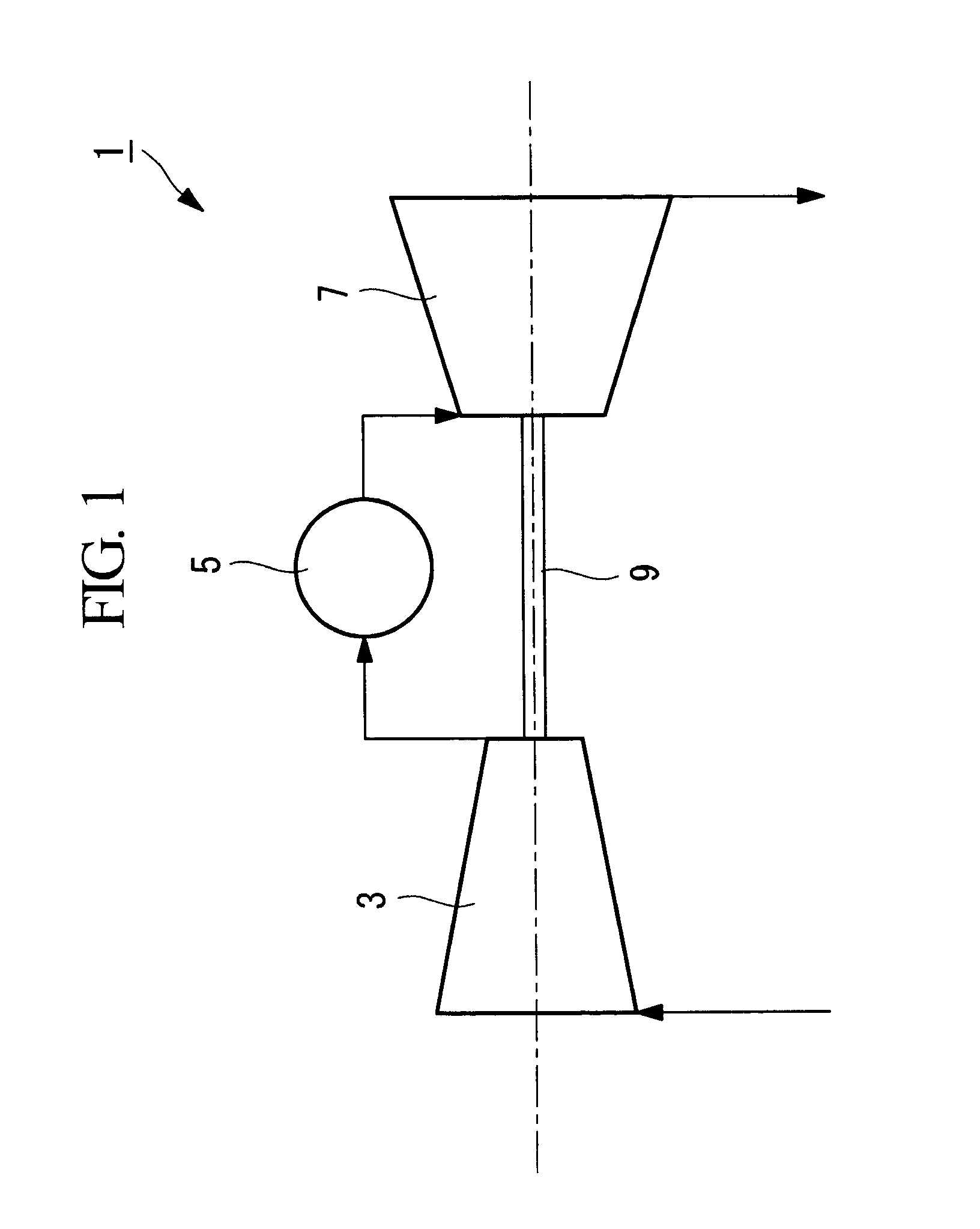
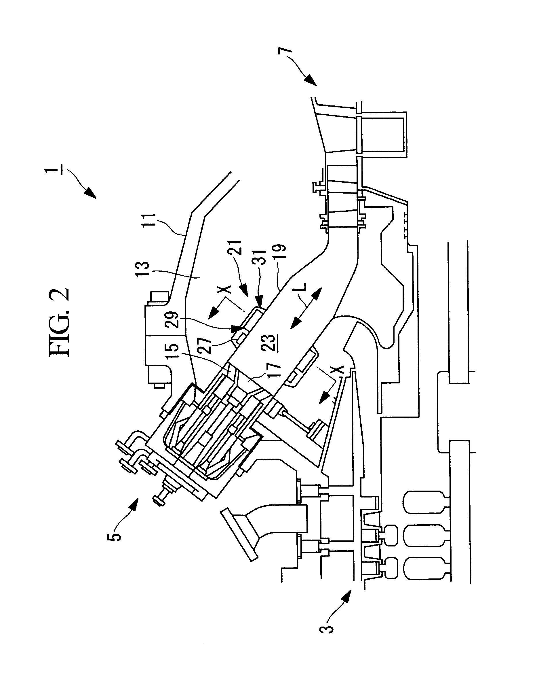
[0050]FIG. 1 is a schematic view for describing the configuration of the gas turbine 1 according to this embodiment. FIG. 2 is a schematic view for describing, in outline, the configuration of combustors 5 in FIG. 1.

[0051]As shown in FIGS. 1 and 2, the gas turbine 1 includes a compressor 3, the combustors 5, a turbine unit (turbine) 7, a rotation shaft 9, and a housing 11 that accommodates these components in place.

[0052]The compressor 3 takes in and compresses the atmosphere, which is the outside air, and supplies the compressed air to the combustors 5.

[0053]Note that the configuration of the compressor 3 may be any known one and is not specifically limited.

[0054]As shown in FIG. 1, the combustors 5 generate combustion gas (high-temperature gas) by mixing the air compressed by the compressor 3 and externally supplied fuel and combusting the mixed gaseous mixtu...

second embodiment

[0115]Next, a second embodiment of the present invention will be described with reference to FIGS. 6 and 7.

[0116]Although the basic configuration of the gas turbine according to this embodiment is the same as that according to the first embodiment, the configuration of the attenuating device 21 is different from that according to the first embodiment. Accordingly, in this embodiment, the attenuating device 21, which is different from that according to the first embodiment, will be mainly described, and overlapping descriptions of the other components will be omitted.

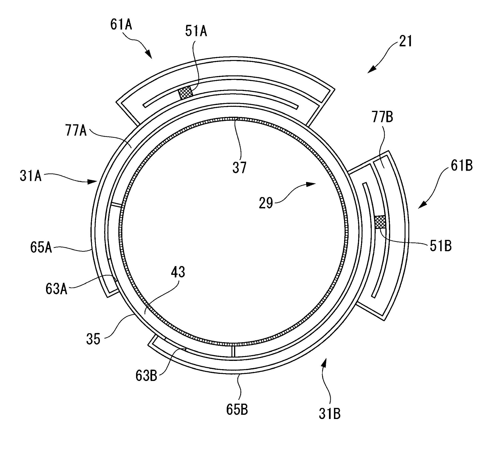
[0117]FIG. 6 is a cross-sectional view for describing the configuration of the relevant part of the attenuating device 21 in the combustor 5 of the gas turbine1 according to this embodiment. FIG. 7 is a cross-sectional view taken along line Z-Z in FIG. 6.

[0118]Note that the components the same as those in the first embodiment will be denoted by the same reference numerals, and the descriptions thereof will be omitted.

[01...

third embodiment

[0134]Next, a third embodiment of the present invention will be described with reference to FIGS. 8 and 9. Although the basic configuration of the gas turbine according to this embodiment is the same as that according to the first embodiment, the configuration of the attenuating device 21 is different from that according to the first embodiment. Accordingly, in this embodiment, the attenuating device 21, which is different from that according to the first embodiment, will be mainly described, and overlapping descriptions of the other components will be omitted.

[0135]FIG. 8 is a cross-sectional view for describing the configuration of the relevant part of the attenuating device 21 in the combustor 5 of the gas turbine 1 according to this embodiment. FIG. 9 is a cross-sectional view taken along line W-W in FIG. 8. Note that the components the same as those in the first embodiment will be denoted by the same reference numerals, and the descriptions thereof will be omitted.

[0136]The aco...


PUM


Abstract

An object is to provide a combustor that requires a small mounting space for an acoustic damper, that can achieve size reduction, and that can improve the ease of maintenance. A combustor (5) of the present invention includes a combustion cylinder (19) that defines a combustion area (23) therein and an acoustic damper (31) that has a damper cover having an acoustic-damper resonance space communicating with the combustion area (23). The damper cover is provided along the combustion cylinder (19) so as to extend in a direction intersecting an axial direction (L) of the combustion cylinder (19).

Description

TECHNICAL FIELD[0001]The present invention relates to a combustor and a gas turbine having the same.BACKGROUND ART[0002]A gas turbine includes a compressor, a combustor, and a turbine. The compressor takes in air, compresses the air to increase its pressure, and directs the high-pressure air to the combustor.[0003]In the combustor, fuel is sprayed into the high-pressure air to combust the fuel. High-temperature combustion gas generated by the combustion of the fuel is directed to the turbine, and this high-temperature combustion gas drives the turbine.[0004]Because the turbine and the compressor rotate about the same rotation shaft, this driving of the turbine drives the compressor, causing the compressor to take in and compress air, as described above.[0005]The gas turbine operating as above may suffer from combustion oscillations during combustion of the fuel, and such combustion oscillations have been a cause of noise and vibration during operation of the gas turbine.[0006]In par...

Claims


Application Information

Patent Timeline
Patent Type & Authority Applications(United States)
IPC IPC(8): F02K1/82G10K11/16
CPCF01D9/023F01D25/04F23R3/005F23M20/005F23R3/46F23R2900/00014F23R3/06F23R3/16F23R3/42
Inventor NAKAMURA, SOSUKEKINOSHITA, TAIKIONO, MASAKIMATSUYAMA, KEISUKETANIGUCHI, KENTA
Owner MITSUBISHI POWER LTD
Why Eureka
Try Eureka