Stator section for an axial flux electric machine with liquid cooling system

a technology of liquid cooling system and which is applied in the direction of dynamo-electric machines, electrical apparatus, windings, etc., can solve the problems of power loss, heat being given off, and trying to break the axial flux electric machine and reducing the effect, so as to achieve more effective cooling and be easy to mak

Inactive Publication Date: 2011-09-15
LUCCHI FABIO
View PDF15 Cites 33 Cited by
  • Summary
  • Abstract
  • Description
  • Claims
  • Application Information

AI Technical Summary

Benefits of technology

[0024]In particular, this invention has for an aim to provide a stator section for an axial flux electric machine with liquid cooling system that permits more effective cooling especially of the electrical conductor coils. Another aim of the invention is to provide a stator section for an axial flux electric machine with liquid cooling system that is versatile and adaptable to most stator structures for axial flux electric machines.
[0025]Yet another aim of the invention is to provide a stator section for an axial flux electric machine with liquid cooling system that is easy to make.

Problems solved by technology

In this way, the interfaces between one strip and the next are distributed crossways relative to the path that would be followed by the eddy current rings, thus tending to break it and to reduce its effect.
During operation of the electric machine, power losses occur in the electrical circuit and in the magnetic circuit and, more specifically:“copper losses” (that is to say, power losses in the electrical circuit of the machine, due to the Joule effect created mainly by the current flowing through the windings and in the electrical conductors);“core losses” (that is to say, power losses in the magnetic circuit of the machine due mainly to the magnetic hysteresis of the magnetic materials and to eddy currents generated in the active parts of the machine, especially in the stator section, that is, core and coils).
These power losses result in heat being given off.
This heat must be removed to the surrounding atmosphere as effectively as possible because excessively high temperatures in the active parts of the machine (core and coils in the stator section) can damage and reduce the efficiency of the electrically insulating components, which are the most sensitive in terms of temperature limits.
In addition, the casing has a complex structure that is difficult to make.
Machining the side of the casing that faces the outer heads of the coils is a particularly complex process.
The interior annular channel is also difficult to make and must be adapted for each different stator size and type.

Method used


Image

  • Stator section for an axial flux electric machine with liquid cooling system
  • Stator section for an axial flux electric machine with liquid cooling system
  • Stator section for an axial flux electric machine with liquid cooling system

Examples


Embodiment Construction

[0041]In the description which follows and in the drawings, identical or corresponding parts in the different embodiments described are, unless otherwise specified, identified by the same reference characters.

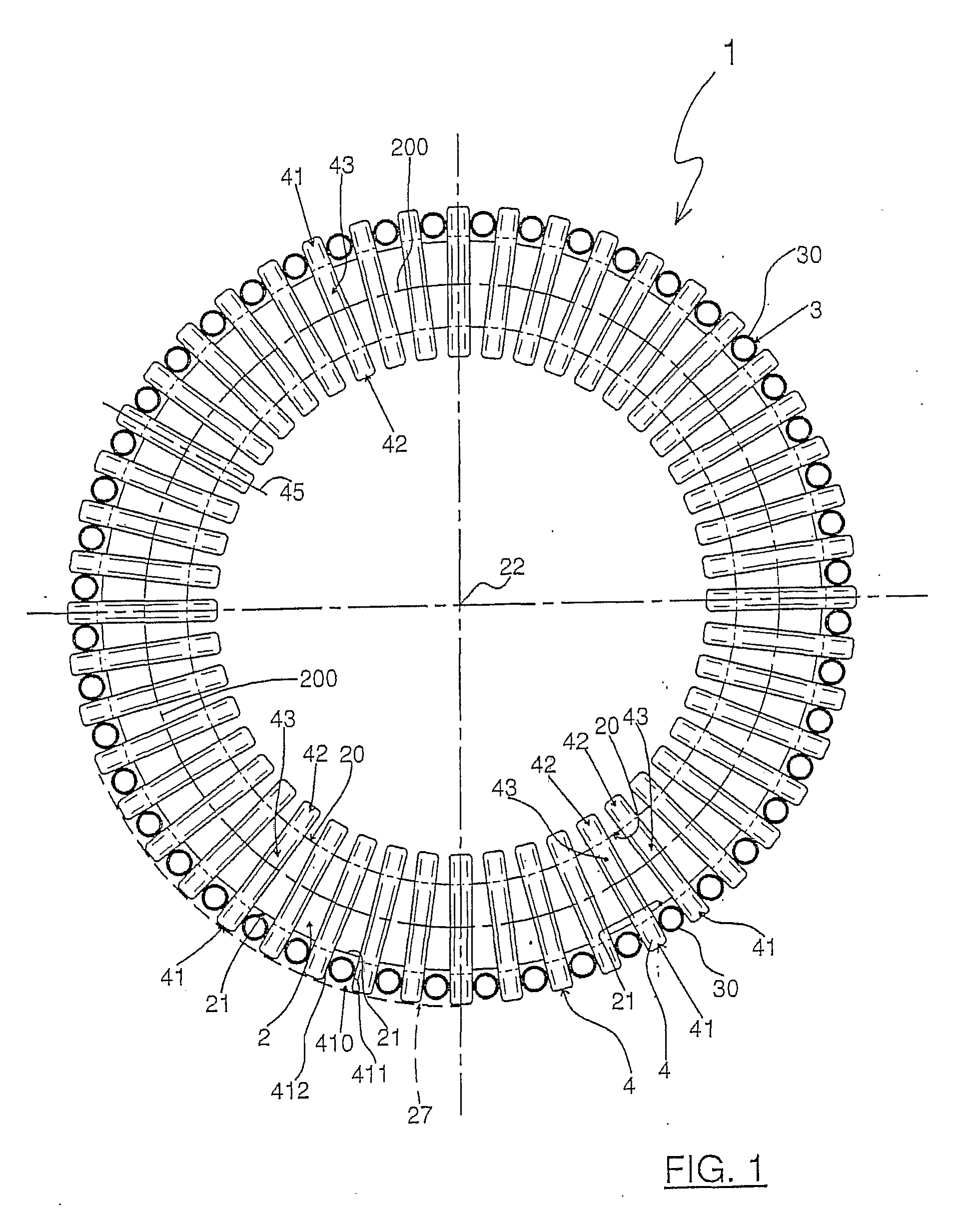
[0042]With reference to the accompanying drawings, the numeral 1 denotes a stator section for an axial flux electric machine with liquid cooling system.

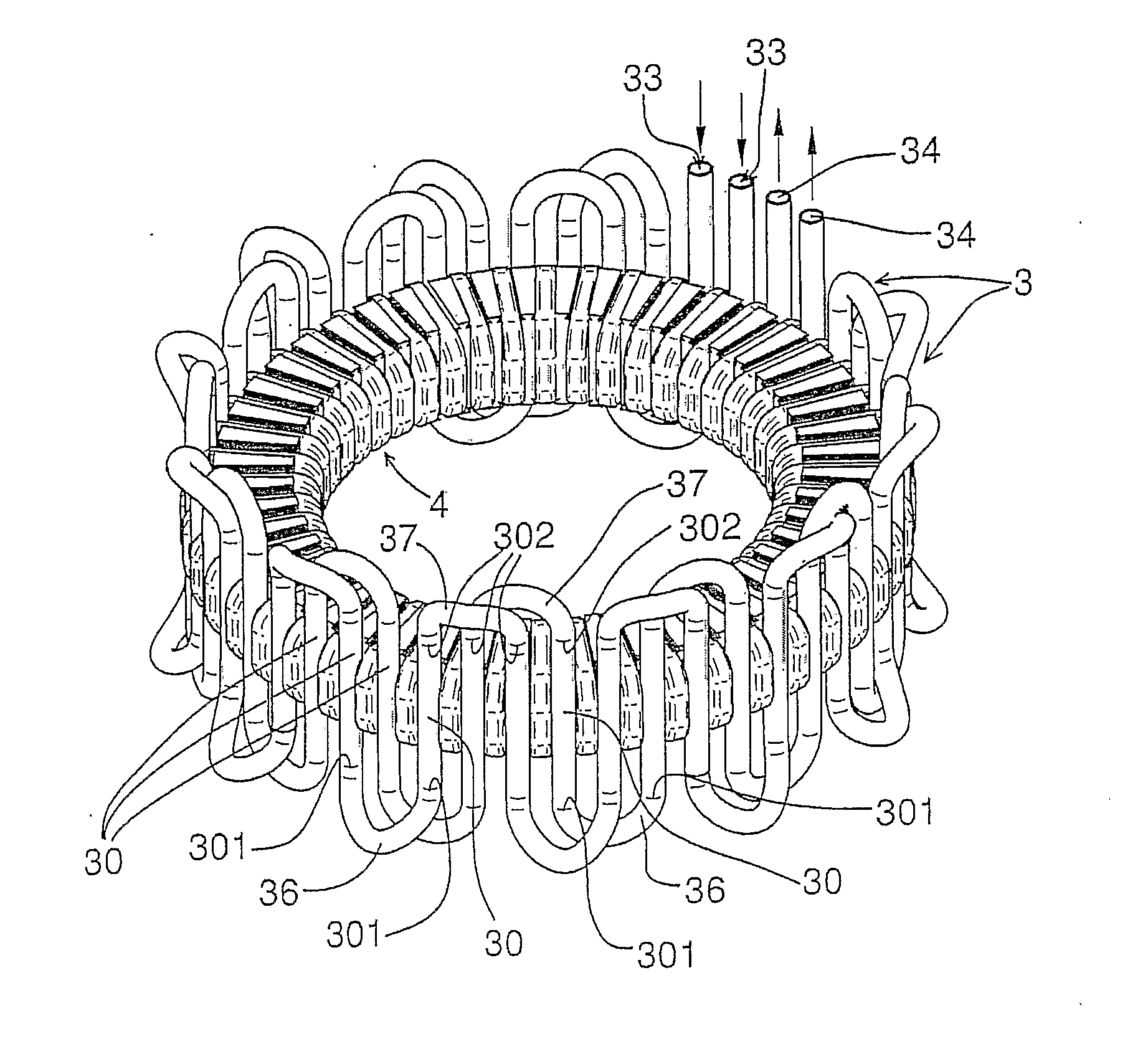
[0043]The stator section 1 comprises a toroidal core 2 having an inside cylindrical surface 20 and an outside cylindrical surface 21 coaxial with each other along a reference axis 22 which is to be made coincide with the axis of rotation of a rotor section of an axial flux electric machine.

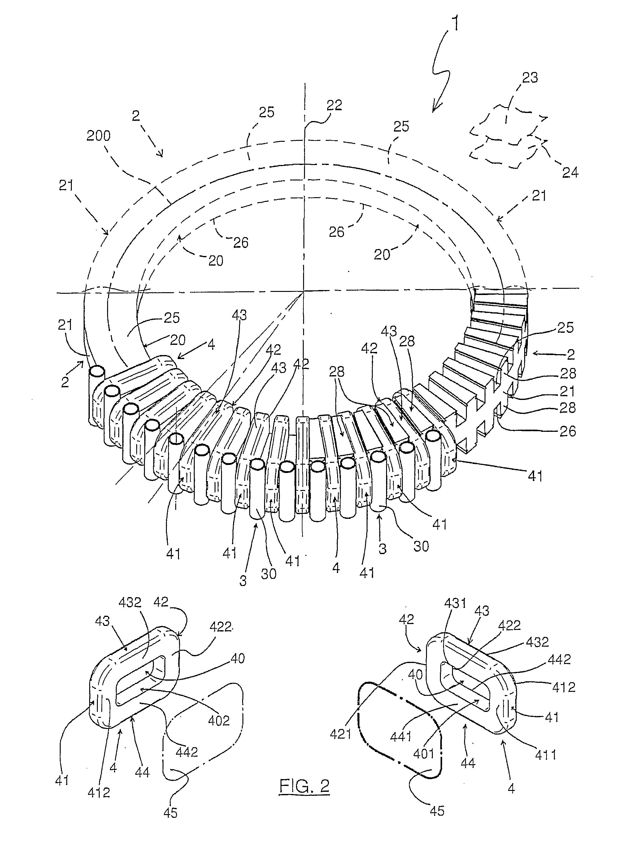
[0044]The stator section 1 also comprises a plurality of electrical conductor coils 4 spaced from each other and distributed along the annular centre line 200 of the core 2.

[0045]With reference in particular (but not only), to FIGS. 2, 7 and 8, each coil 4 has the shape of a solid with a hole 40 passing through it. Thus, each coil 4 has an ind...


PUM


Abstract

In a stator section (1) of an axial flux electric machine with liquid cooling system, a toroidal core (2) having an inside cylindrical surface (20) and an outside cylindrical surface (21) coaxial with each other along a reference axis (22), is provided along its annular centre line (200) with a plurality of electrical conductor coils (4) spaced from each other and each placed around the core (2) with a first face of it (41) lying on the outside cylindrical surface (21), a second face of it (42) lying on the inside cylindrical surface (20) and a third and fourth face of it (43, 44) lying transversally to the first and second faces (41, 42). Each cooling duct section (30) of a plurality of cooling duct sections (30) produces a movement of the liquid coolant from a first base surface (25) of the core (2) to a second base surface (26) of the core (2) and is located between the two first faces (41) of two consecutive coils (4) or between the two second faces (42) of two consecutive coils (4). At least the first or the second face (41, 42) of any one coil (4) of the plurality of coils (4) is adjacent to and in contact with at least one respective cooling duct section (30) of the plurality of cooling duct sections (30).

Description

TECHNICAL FIELD[0001]This invention relates to a stator section for an axial flux electric machine with liquid cooling system.BACKGROUND ART[0002]Generally speaking, an electric machine comprises a stationary part, commonly referred to as “stator section” (or simply “stator”), and a mobile part, both equipped with windings of electrical conductor and / or sources of a magnetic and / or electromagnetic field. Together with the machine structure, these windings and sources always form both an electric circuit (defined as an assembly of structures and materials with an electric current and / or an electric field flowing through it) and a magnetic circuit (defined as an assembly of structures and materials with a magnetic field flowing through it). In order to operate, the electric machine uses electromagnetic induction (produced by the concatenation of magnetic field fluxes with the electric windings) and / or electromagnetic forces (generated by the magnetic / electromagnetic field sources on t...

Claims


Application Information

Patent Timeline
Patent Type & Authority Applications(United States)
IPC IPC(8): H02K3/24
CPCH02K3/24H02K9/19H02K3/46H02K9/197
Inventor LUCCHI, FABIO
Owner LUCCHI FABIO
Why Eureka
Try Eureka