Motor control method and apparatus and electric power steering system

Inactive Publication Date: 2011-09-15
DENSO CORP
View PDF1 Cites 29 Cited by
  • Summary
  • Abstract
  • Description
  • Claims
  • Application Information

AI Technical Summary

Benefits of technology

[0011]It is therefore an object of the present invention to provide a motor control method and a motor control apparatus, which reduce torque ripple near a zero-cross point in dead time compensation control, while

Problems solved by technology

However, a short time delay arises at the time of switching between turning on and off.
Since this dead time causes loss of an output voltage of the inverter, an error arises between a PWM command value and the output voltage actually produced by the inverter.
According to the dead time compensation by improving the response characteristic of the current loop in the PI control, the motor, which is PI-controlled, is likely to vibrate and generate abnormal sound, because noise component is increased if the loop gain in feedback control is increased.
In case that the motor is located near passengers in a vehicle compartment as in an electric powe

Method used


Image

  • Motor control method and apparatus and electric power steering system
  • Motor control method and apparatus and electric power steering system
  • Motor control method and apparatus and electric power steering system

Examples


first embodiment

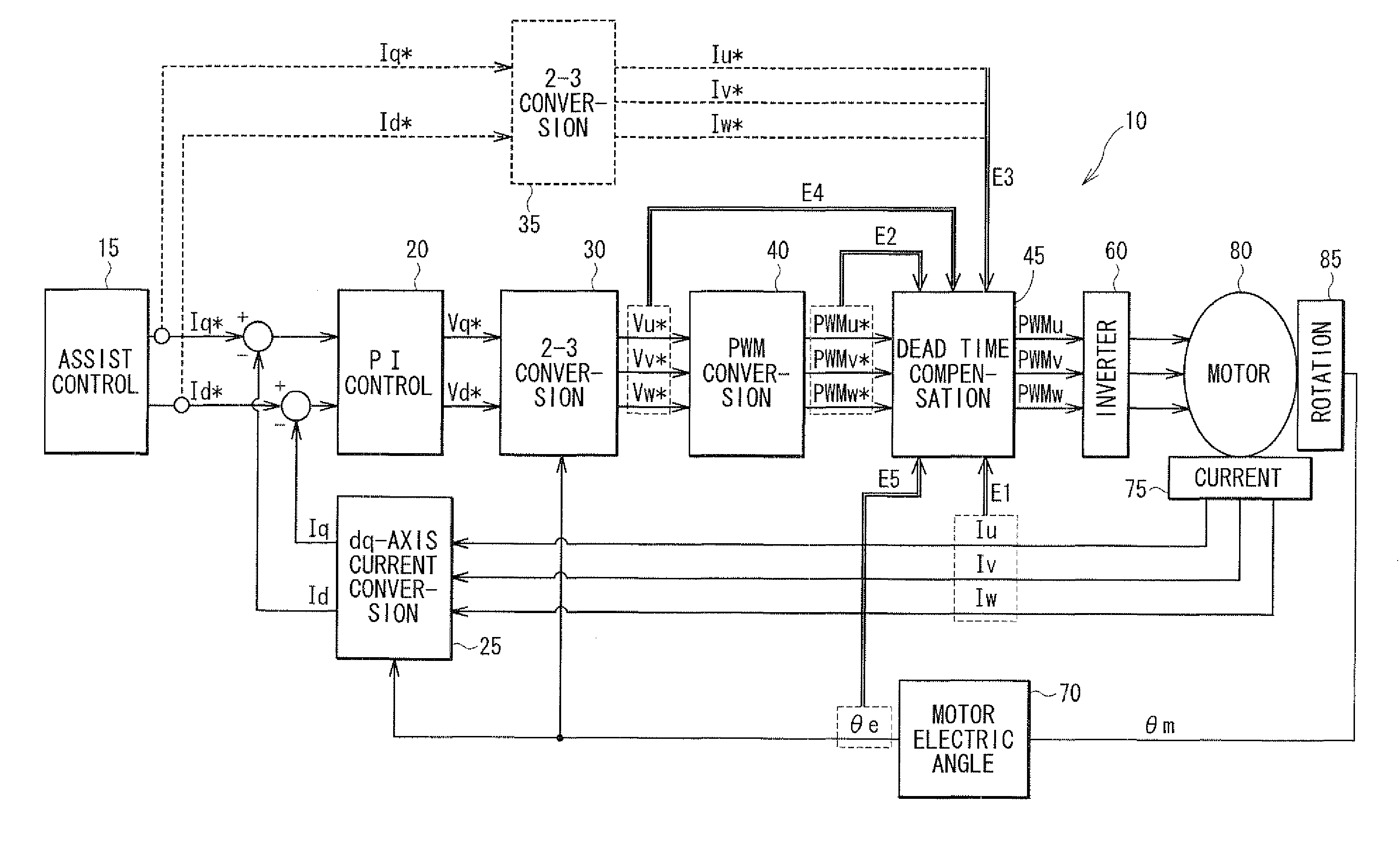
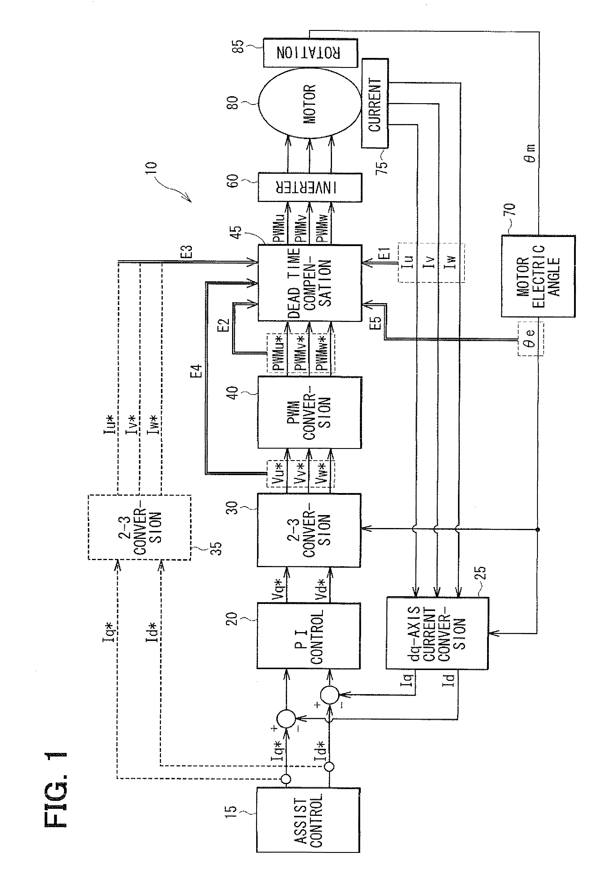
[0045]In the motor control method according to the first embodiment, the dead time compensation value DV for the U-phase is determined as shown in FIG. 4. In FIG. 4, symbol S denotes a step, symbol Vs denotes a reference value of the dead time compensation value and symbol 2Vs denotes a doubled compensation value, which is two times as large as Vs. The parameter ψ(θe)u is a function of the electric angle θe of the U-phase. Specifically, it corresponds to the phase current detection value Iu, the PWM command value PWMu*, the phase current command value Iu*, the phase voltage command value Vu* or the like.

[0046]At S11u, it is checked whether the parameter ψ(θe)u of the U-phase is equal to or greater than 0 and other two parameters ψ(θe)v of the V-phase and ψ(θe)w of the W-phase are both less than 0. If the check result of S11u is YES, a first dead time compensation value DVu is set to 2Vs at S12u. If the check result of S11u is NO, S13u is executed. At S13u, it is checked whether the ...

second embodiment

[0061]The motor control apparatus, which performs a motor control method according to a second embodiment, is generally the same as the first embodiment. The motor control method according to the second embodiment is different from the first embodiment in that a present section is determined directly from an electric angle θe and not from the parameter of each phase.

[0062]Dead time compensation values DVu, DVv and DVw of a U-phase, a V-phase and a W-phase are determined as shown in FIGS. 10, 11 and 12 in a motor control method according to the second embodiment, respectively.

[0063]The dead time compensation value DVu for the U-phase is determined as shown in the flowchart of FIG. 10. At S21u, it is checked whether the electric angle θe is equal to or greater than 60° and less that 120°. If the check result of S21u is YES, the first dead time compensation value DVu is set to 2Vs at S22u. If the check result of S21u is NO, S23u is executed. At S23u, it is checked whether the electric ...


PUM


Abstract

In a motor control method for driving a three-phase motor by an inverter, a dead time compensation operation is performed to compensate for output voltage loss caused by a dead time, in which both a high-side FET and a low-side FET in the inverter are turned off. For example, in a range between 0° and 60° and a range between 120° and 180°, a reference value is provided stepwise to a PWM command value of a U-phase. In a range between 60° and 120°, a doubled reference value is provided stepwise to the PWM command value. A compensated PWM voltage is supplied to the inverter. The stepwise change at zero-cross points, 0° and 180°, is reduced relative to a case, in which a fixed dead time compensation value is provided in a range between 0° and 180°. Torque ripple near the zero-cross point is thus suppressed.

Description

CROSS REFERENCE TO RELATED APPLICATION[0001]This application is based on and incorporates herein by reference Japanese patent application No. 2010-51584 filed on Mar. 9, 2010.FIELD OF THE INVENTION[0002]The present invention relates to a motor control method and a motor control apparatus, which perform dead time compensation of a motor driven by an inverter. The present invention also relates to an electric power steering system using such a control method and a control apparatus.BACKGROUND OF THE INVENTION[0003]A voltage-type PWM inverter has conventionally been used as a drive apparatus for a three-phase motor. The voltage-type PWM inverter generally has an inverse transformation circuit including high-side arms and low-side arms. Each high-side arm is formed of a high-side FET, which is a switching element at a power supply voltage side (high potential side). Each low-side arm is formed of a low-side FET, which is a switching element at a ground side (low potential side).[0004]If...

Claims


Application Information

Patent Timeline
IPC IPC(8): H02P27/04B62D5/04B62D6/00B62D119/00H02P21/00H02P23/07H02P27/08
CPCB62D5/046H02M7/53875H02P27/08H02P21/0003H02M2001/385H02M1/385
Inventor HAYASHI, YOSHITAKA
Owner DENSO CORP
Why Eureka
Try Eureka