
Sensor Circuit

a sensor circuit and circuit technology, applied in the direction of pulse automatic control, indicating the presence of current/voltage, instruments, etc., can solve the problems of disassembly and maintenance of other circuit elements, and the examinee to feel the displeasure and inconvenience of a measurement procedure,

Inactive Publication Date: 2011-09-22
LAXTHA
View PDF6 Cites 5 Cited by
  • Summary
  • Abstract
  • Description
  • Claims
  • Application Information

AI Technical Summary

Benefits of technology

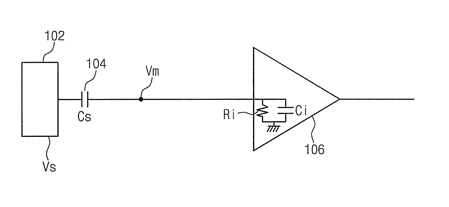
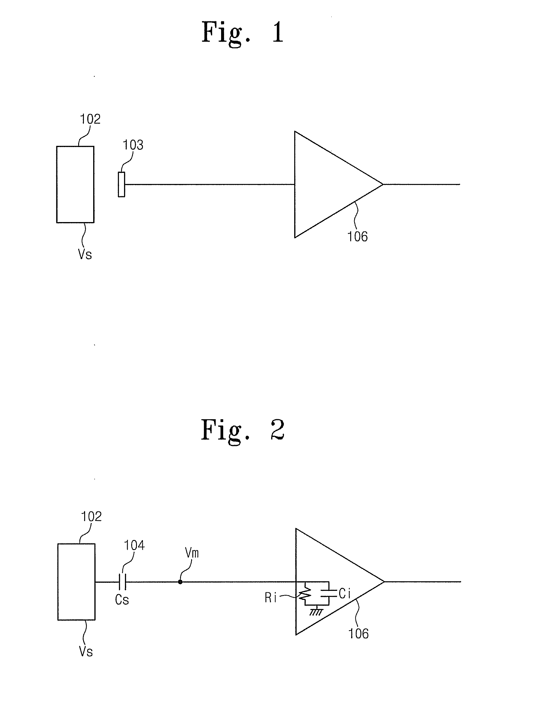
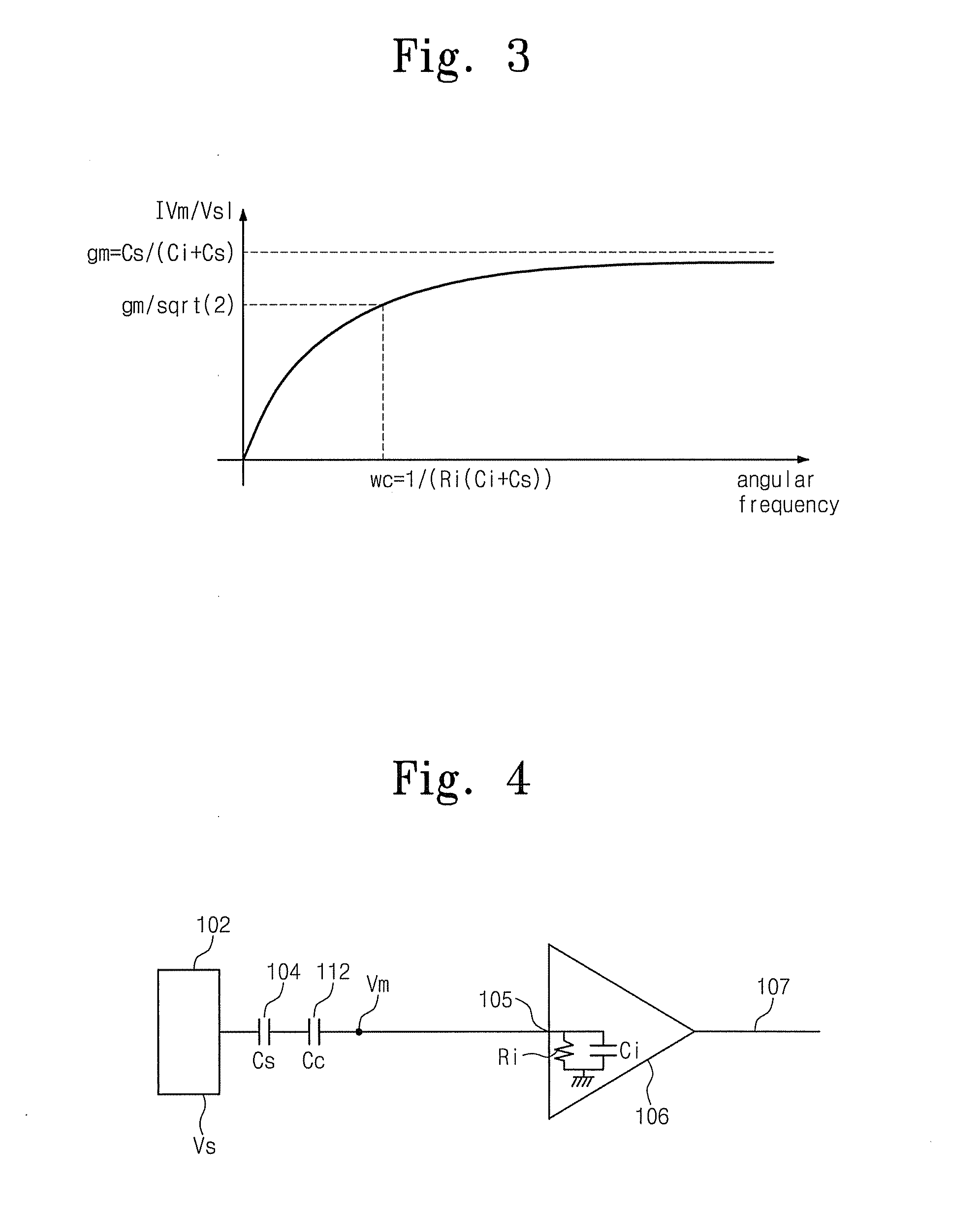
[0012]According to an example embodiment, the first current source may increase an equivalent input resistance of the sensor circuit.
[0013]According to an example embodiment, the second current source may decrease an equivalent input capacitance of the sensor circuit.
[0014]According to an example embodiment, the bias current source may provide a stable operation of the first amplifier.

Problems solved by technology

Especially, because an input impedance of an operational amplifier used in electrical signal measurement is an input impedance of a sensor circuit, other circuit elements are almost not available as impedance rising elements.
Electrolyte electrode attached to a skin of an examinee may cause the examinee to feel displeasure and inconvenience of a measurement procedure.
Inconvenience of a measurement procedure and the examinee's displeasure serve as an obstacle to drastic demand for utilization of a bioelectrical signal.

Method used


Image

  • Sensor Circuit
  • Sensor Circuit
  • Sensor Circuit

Examples


Embodiment Construction

[0032]The present invention will now be described more fully hereinafter with reference to the accompanying drawings, in which preferred embodiments of the present invention are shown. However, the present invention may be embodied in many different forms and should not be construed as limited to the embodiments set forth herein. Rather, these embodiments are provided so that this disclosure will be thorough and complete, and will fully convey the scope of the present invention to those skilled in the art. In the drawings, the thicknesses of layers and regions are exaggerated for clarity. It will also be understood that when a layer is referred to as being “on” another layer or substrate, it can be directly on the other layer or substrate, or intervening layers may also be present. Like numbers refer to like elements throughout.

[0033]Non-contact bioelectrical signal measurement without use of an electrolyte electrode is required to overcome disadvantages of an electrolyte-containing...


PUM


Abstract

The present invention provides a sensor circuit. The sensor circuit comprises a first amplifier which receives a measurement signal via an input end thereof, amplifies the received signal, and outputs the amplified signal via a first output end thereof; a first current source which supplies current (Ir) flowing toward the input resistance (Ri) of the first amplifier; a second current source which supplies current (Ic) flowing toward the input capacitance (Ci) of the first amplifier; and a bias current source which reduces the direct current offset voltage in the output of the first amplifier.

Description

CROSS-REFERENCE TO RELATED APPLICATIONS[0001]This U.S. non-provisional patent application claims priority under 35 U.S.C. §119 to Korean Patent Application No. 10-2008-0117484, filed on Nov. 25, 2008, and Korean Patent Application No. 10-2009-0008517, filed on Feb. 3, 2009, the entirely of which is hereby incorporated by reference.FIELD OF THE INVENTION[0002]The present invention relates to sensor circuits and, more particularly, to a electrical potential sensor circuit.BACKGROUND OF THE INVENTION[0003]When an impedance of a signal source in an electrical signal is high, an input impedance of an amplifier must be considerable high to measure an electrical signal without loss. High input impedance amplifiers have been developed for signal measurement in an electrical signal measurement field. In the case that the amplifier is an operational amplifier, an input impedance of a sensor circuit is nearly decided by a self input impedance of the operational amplifier. Especially, because a...

Claims


Application Information

Patent Timeline
Patent Type & Authority Applications(United States)
IPC IPC(8): G01R19/145H03F1/00
CPCH03F1/34H03F2200/375H03F2200/261H03F3/45
Inventor KIM, MINCHEOL
Owner LAXTHA
Learn More