Adjustable Beam Size Illumination Optical Apparatus and Beam Size Adjusting Method

a technology of illumination optical apparatus and beam size, which is applied in the direction of fixed installation, lighting and heating apparatus, instruments, etc., can solve the problem of unwasteful use of incident energy

Inactive Publication Date: 2011-09-22
HITACHI SEIKO LTD
View PDF9 Cites 24 Cited by
  • Summary
  • Abstract
  • Description
  • Claims
  • Application Information

AI Technical Summary

Benefits of technology

[0035]According to the invention, only if the lens interval of one of the cylindrical array lens group and the cylindrical telescope lens group is changed, the beam size on the projection surface can be changed in t

Problems solved by technology

On the other hand, due to high running cost of the short-wavelength light source

Method used


Image

  • Adjustable Beam Size Illumination Optical Apparatus and Beam Size Adjusting Method
  • Adjustable Beam Size Illumination Optical Apparatus and Beam Size Adjusting Method
  • Adjustable Beam Size Illumination Optical Apparatus and Beam Size Adjusting Method

Examples


example 1

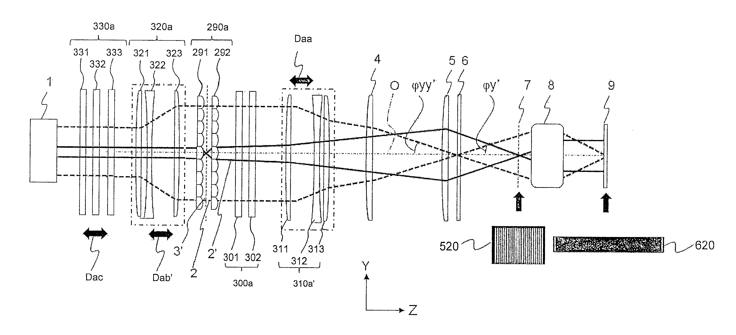
[0091]Example 1 is an example in which aperture angles φx and φy in an adjustable beam size illumination optical system are changed to change the beam size.

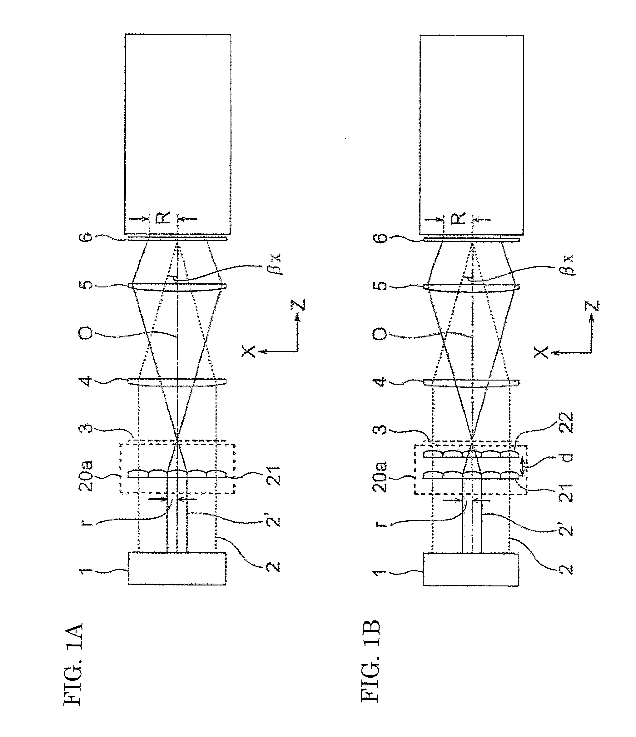
[0092]FIGS. 4A and 4B are explanatory views showing an adjustable beam size illumination optical system according to Example 1. FIG. 4A shows an XZ section of the beam size varying illumination optical system. FIG. 9B shows a YZ section of the adjustable beam size illumination optical system. In the following description, a suffix “′” attached to a lens system means that an interval between lenses has been changed.

[0093]In FIG. 9A, the adjustable beam size illumination optical system is constituted by an illumination optical system and a projection optical system. The illumination optical system includes a light source 1, two long-axis-direction cylindrical array lenses 21 and 22, and a condenser lens 4. The light source 1 such as an excimer laser or a mercury lamp forms parallel light. The two long-axis-direction cylindrical arr...

example 2

[0099]FIGS. 6A and 6B are explanatory views showing an adjustable beam size illumination optical system according to Example 2. FIG. 6A shows an XZ section of the adjustable beam size illumination optical system. FIG. 68 shows a YZ section of the adjustable beam size illumination optical system. In Example 2, the cylindrical telescope lens group 30a is rotated by 90° with respect to Example 1 so as to serve as a long-axis-direction cylindrical telescope lens group 40b, 40b′. The other constituent portions, which are equivalent to those in Example 1, are referred to by the same numerals and signs correspondingly, and redundant description thereof will be omitted.

[0100]In Example 2, the beam size is changed as follows. That is, when a lens interval Dc between adjacent ones of three long-axis-direction cylindrical telescope lenses 41, 42 and 43 of the long-axis-direction cylindrical telescope lens group 40b′ is changed for the beam size in the long axis (X) direction, and a lens interv...

example 3

[0103]FIGS. 7A and 7B are explanatory views showing an adjustable beam size illumination optical system according to Example 3. FIG. 7A shows an XZ section of the adjustable beam size illumination optical system. FIG. 7B shows a YZ section of the adjustable beam size illumination optical system. In Example 3, the cylindrical array lens 12 is removed from the cylindrical array lens group 10b′ in Example 1 to leave only the cylindrical array lens 11 as a short-axis-direction cylindrical array lens (depicted as cylindrical array lens group 10c in FIGS. 7A and 7B). A lens interval De of a long-axis-direction cylindrical array lens group 20c′ is changed for the beam size in the long axis (X) direction and a lens interval Df of a short-axis-direction cylindrical telescope lens group 30c′ is changed for the beam size in the short axis (Y) direction. Thus, aperture angles φx and φy in the X and Y directions are changed to change the beam size.

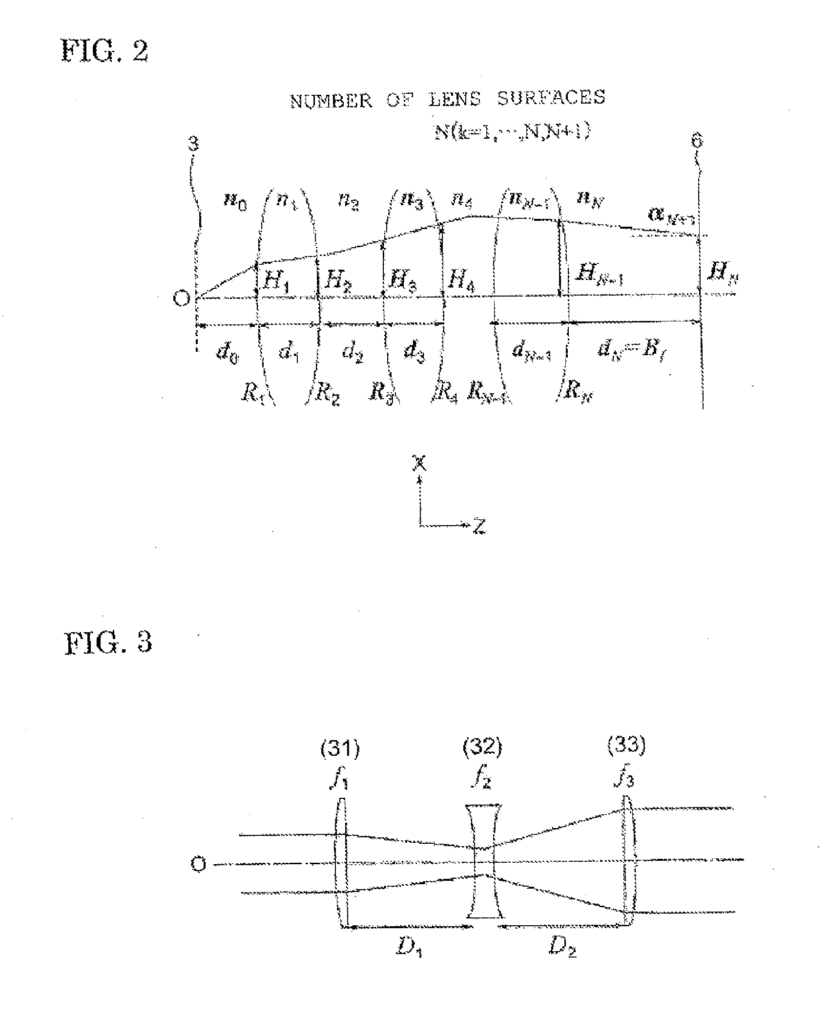
[0104]In Example 3, similarly to Example 1, foca...


PUM

PropertyMeasurementUnit
Angleaaaaaaaaaa
Sizeaaaaaaaaaa

Abstract

An adjustable beam size illumination optical apparatus includes a beam size adjusting optical system which includes groups of cylindrical array lenses disposed correspondingly to the long and short axis directions respectively and having variable intervals among the lenses, and a group of cylindrical telescope lenses disposed correspondingly to one of the long and short axis directions and having variable intervals among the lenses, and adjusts parallel light from a light source in size in accordance with the two axis directions orthogonal to each other. The lens interval of one of the cylindrical array lens groups and the cylindrical telescope lens group is changed to adjust a beam size on a projection surface in accordance with the long axis direction or the short axis direction. Thus, it is possible to adjust the beam size in accordance with the long axis direction and the short axis direction individually, and it is possible to make irradiation with the beam with uniform intensity.

Description

BACKGROUND OF THE INVENTION[0001]1. Field of the Invention[0002]The present invention relates to an adjustable beam size illumination optical apparatus which includes an adjustable beam size illumination optical system for adjusting a beam size in a long axis direction and a short axis direction individually, and a beam size adjusting method to be carried out in the apparatus.[0003]2. Description of the Background Art[0004]To meet the future trend of printed board wiring which will be made finer, a laser machining apparatus which has been heretofore applied to drilling is also required to be applied to wiring pattern grooving. In the apparatus, a circuit pattern on a mask is imaged on a substrate by a projection lens, and the substrate is stage-scanned with slit illumination light, with which the substrate is machined directly. In the apparatus, a short-wavelength light source is used as a light source in consideration of machinability.[0005]Since semiconductor chips have various sh...

Claims


Application Information

Patent Timeline
IPC IPC(8): F21V5/04G02B3/00G02B3/06G02B13/08G02B15/00G02B19/00
CPCG02B27/0955G02B27/18B23K26/064
Inventor YOSHIMIZU, KEIKOAOYAMA, HIROSHIMARUYAMA, SHIGENOBUYOSHITAKE, YASUHIRO
Owner HITACHI SEIKO LTD
Why Eureka
Try Eureka