System and method for creating liquid droplet impact forced collapse of laser nanoparticle nucleated cavities

a laser nanoparticle and nucleated cavity technology, applied in nuclear targets, nuclear reactors, greenhouse gas reduction, etc., can solve the problems of acoustic inertial confinement fusion not winning widespread credibility, a large amount of energy, control loss, etc., to enhance the implosion energy of the cavity collapse, the effect of enhancing the collapse energy

Inactive Publication Date: 2011-09-22
SYNERGY INNOVATIONS INC
View PDF5 Cites 37 Cited by
  • Summary
  • Abstract
  • Description
  • Claims
  • Application Information

AI Technical Summary

Benefits of technology

[0014]The present invention is a novel device, system, and method for causing the forced collapse of vapor cavities within liquid droplets. The exemplary device may have an injection means for injecting nanoparticles into a liquid or the device may employ a previously-mixed liquid. A plenum and one or more nozzles may eject a jet or a multitude of jets comprising liquid and nanoparticle material. Droplets are produced from the breakup of the jet. In one embodiment, an irradiating device exposes the droplets to electromagnetic waves to produce and expand cavities in the droplets by heating the nanoparticles. The droplets are collided into a suitable (for example, solid) target in order to enhance the collapse of the cavities inside the droplets. The irradiating and colliding are timed to enhance implosion energy of the cavities' collapse. In another embodiment wherein the droplets contain an emulsion of, for example, a volatile fluid, no irradiation is necessary. In yet another embodiment, the droplets contain an emulsion of a volatile fluid and also include a nanoparticle. In this embodiment, irradiation is required to gain the additional benefit of a cavity caused by irradiating the nanoparticle.

Problems solved by technology

Thus, combining (for example) two Hydrogen atoms to create Helium yields an enormous amount of energy.
First, the energy generated by the implosion must be well in excess of the required energies for initiating the fusion reactions.
Assuming such energies are achievable, if the size scale of individual implosions and targets is too large, control is lost.
While very different from the concept disclosed herein, it is important to note that such acoustic inertial confinement fusion has not won widespread credibility.
Furthermore, even granting that nuclear fusion has indeed been achieved as claimed, both power scale-up and size scale-up are intrinsically difficult for acoustic systems, limited as they are by the requirements that the wavelength be much larger than the cavity radius, and by inherent nonlinear acoustic propagation saturation as power input to the transducers increases.
The prior art in this area of technology has suffered from several drawbacks including, but not limited to, the need to use a complex driver, such as a high frequency ultrasonic generator, or the like, for causing formation of the slugs or droplets.
Further, without a driver, other prior art devices are unsuitable for this application due to the fact that the distance required for a stream of liquid to break up into droplets is so long that the stream atomizes to a mist instead of forming droplets.
The challenge then became how to create cavities inside the very-high-speed droplets driven by ultra-high pressure in the nozzle plenum chamber.
However, the emulsion technique described above suffers from a lack of control over the timing and size of the resultant cavities, which begin to form from the emulsified phase micro droplets within the host liquid as the pressure decreases when the jet exits the high-pressure nozzle.
Further, such cavities contain the entire volume of vaporized volatile compound, and their ensuing collapse may be damped by the cushioning effect of so much vapor in the interior.

Method used


Image

  • System and method for creating liquid droplet impact forced collapse of laser nanoparticle nucleated cavities
  • System and method for creating liquid droplet impact forced collapse of laser nanoparticle nucleated cavities
  • System and method for creating liquid droplet impact forced collapse of laser nanoparticle nucleated cavities

Examples


Embodiment Construction

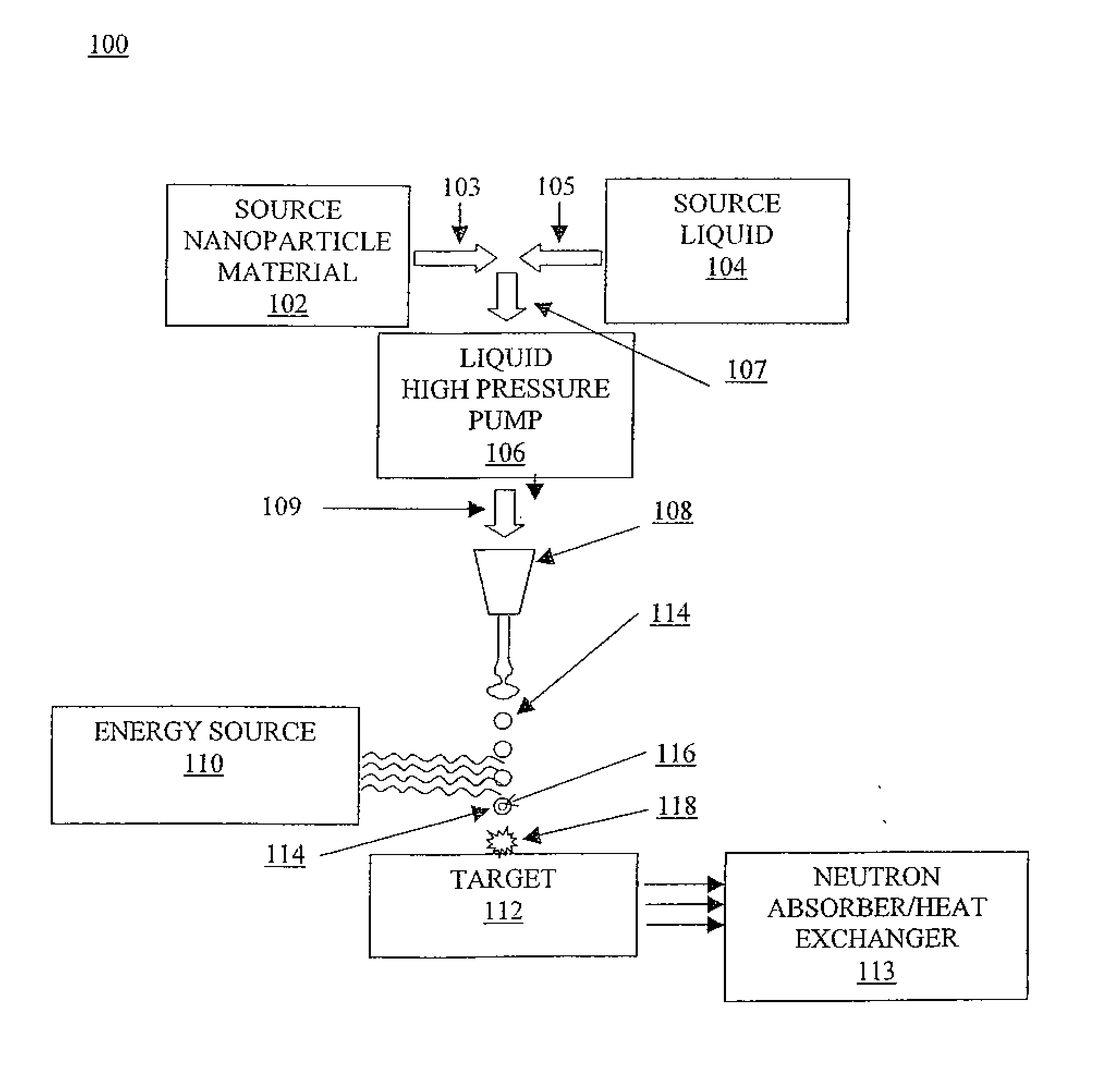
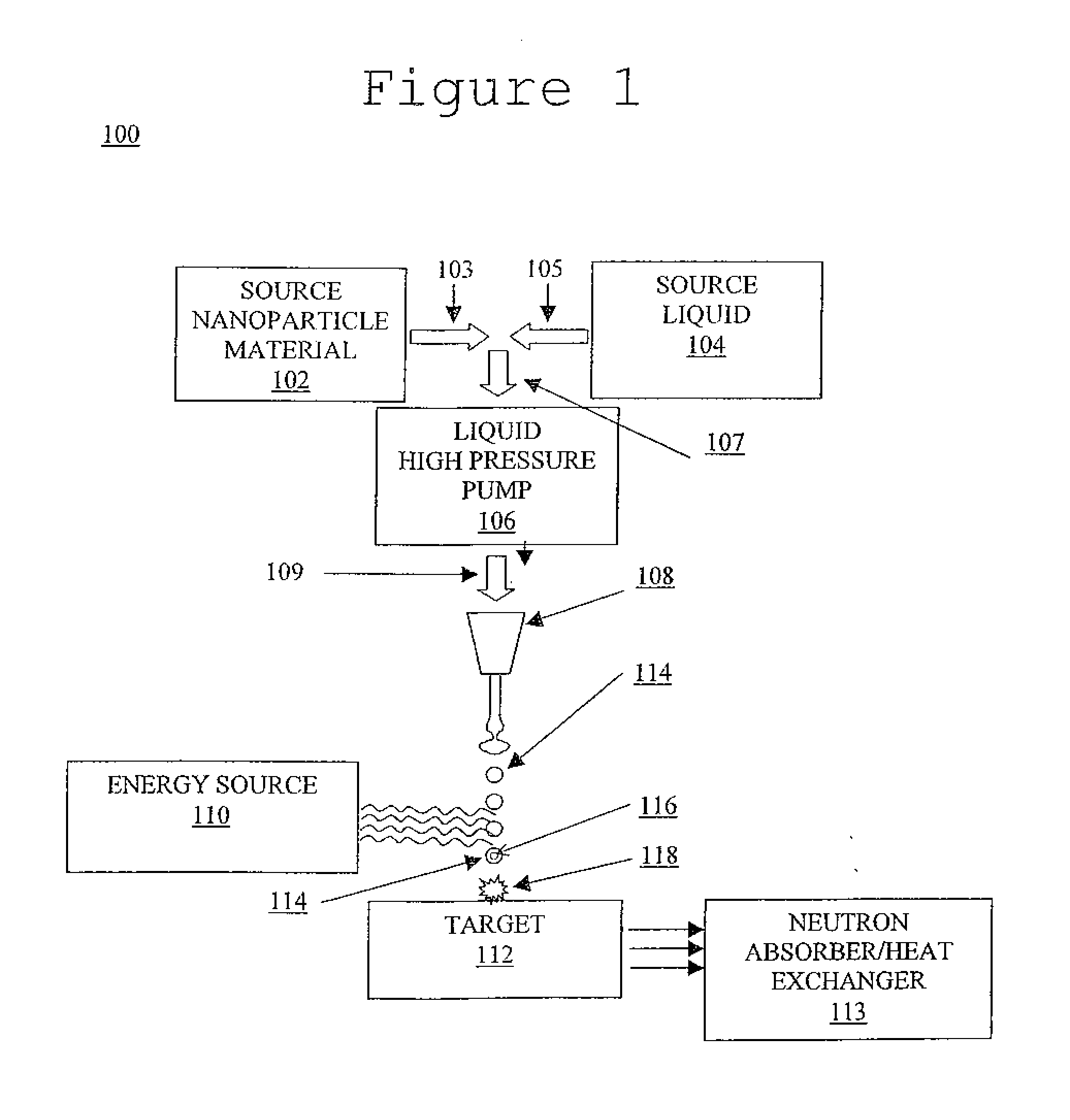
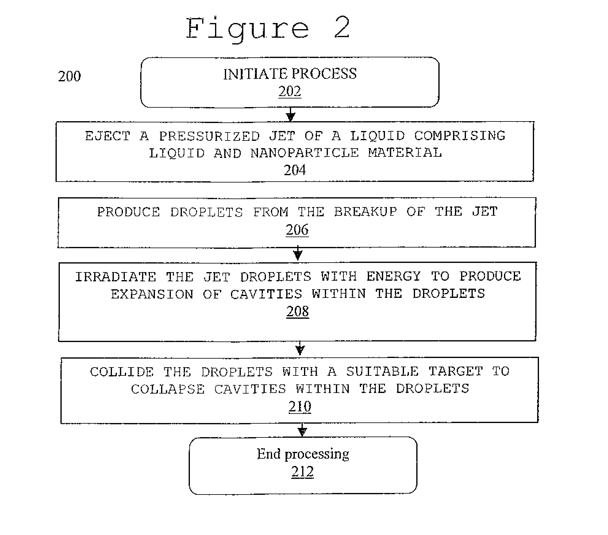
[0021]The invention disclosed herein rests in the union of two different technologies. The first technology relates to creating temporally, spatially and energetically controlled cavities in a liquid. The second technology relates to creating small, high-velocity droplets as disclosed, for example, in co-pending U.S. patent application Ser. No. 11 / 075,833 incorporated fully herein by reference. By combining these two technologies, cavities can be induced in high-velocity droplets with precise timing of their inception and expansion to a preferred radius. Upon impact of these cavity-containing droplets with a target, strong compressional waves are created which then rapidly propagate into the interior of the drop. Rapid inertial collapse of a cavity will be forced by the great positive pressure rise across the compressional wave, driving the cavity to collapse more violently than it would naturally. With suitable materials comprising the contents of the cavity, the energy during the ...


PUM

PropertyMeasurementUnit
temperatureaaaaaaaaaa

Abstract

A device, method and system for causing a controlled collapse of cavities formed within liquid droplets wherein a pressurized jet comprising a liquid and nanoparticle material produces droplets from the breakup of the jet stream. The liquid droplets may be irradiated with energy to produce and expand cavities formed within the droplets by irradiation of the nanoparticles contained within the droplets or alternatively, a volatile fluid with or without a metal nanoparticle may form the cavity. The droplets are collided with a target to collapse the cavities within the droplets. The irradiating (if provided) and colliding are timed to enhance implosion energy resulting from the cavities' collapse. The implosion energy and the fuel in the cavity may be used to activate and sustain a fusion reaction or from any other purposes.

Description

CROSS REFERENCE TO RELATED APPLICATIONS[0001]This application is a continuation-in-part of U.S. patent application Ser. No. 11 / 696,491, now U.S. Pat. No. 7,445,319 filed Apr. 4, 2007 Entitled “System And Method For Creating Liquid Droplet Impact Forced Collapse Of Laser Nanoparticle Nucleated Cavities For Controlled Nuclear Reactions” which in turn is a continuation-in-part of U.S. patent application Ser. No. 11 / 075,833 filed Feb. 22, 2005 entitled Method And Apparatus For Forming High-Speed Liquid Droplets which is fully incorporated herein by reference.TECHNICAL FIELD[0002]The present invention relates to generating and collapsing cavities in liquid droplets and more particularly, relates to utilizing the energy of the collapse.BACKGROUND INFORMATION[0003]Nuclear fusion describes the class of reactions that combine light atoms (Hydrogen, Deuterium, etc.) to form heavier atoms. For the lightest atoms, the binding energy per nucleon is a sharply increasing function of atomic number ...

Claims


Application Information

Patent Timeline
Patent Type & Authority Applications(United States)
IPC IPC(8): G21B1/00B41J2/015
CPCG21B3/00Y02E30/18H05H6/00Y02E30/10
Inventor DEAN, JR., ROBERT C.HOLT, R. GLYNNROY, RONALD A.
Owner SYNERGY INNOVATIONS INC
Why Eureka
Try Eureka