
In-Line Legged Robot Vehicle and Method for Operating

a robot and in-line technology, applied in the field of legged mobile robots, can solve the problems of increasing the risk of overturning, reducing the usefulness of vehicles, so as to reduce body motion and improve mobility

Active Publication Date: 2011-09-22
GOULDING JOHN R
View PDF5 Cites 213 Cited by
  • Summary
  • Abstract
  • Description
  • Claims
  • Application Information

AI Technical Summary

Benefits of technology

A vehicle with legs can go where wheeled or tracked vehicles cannot go. Legged vehicles have improved mobility over rugged terrain with unstable footholds, such as mountain slopes and piles of rubble. Legged vehicles choose discrete, optimal foot placement and vary the length of the leg with respect to the body. Additionally, legged vehicles can bound, leap, or jump over areas of ground that do not have a continuous path of support or closely spaced footholds. Moreover, legged vehicles are able to move in man-made or cultural environments, traversing obstacles such as curbs, stairs, and narrow passageways. With respect to wheeled vehicles, legged vehicles reduce body motion. This characteristic is especially well suited to the comfort of a rider or passenger.
It is therefore an object of the present invention to solve the problems associated with providing a single track or in-line multi-legged mobile robot similar in form or function to the motorcycle or bicycle but with the added benefit of legs and full or partial robotic control. For example, unlike the wheeled motorcycle or bicycle, a feature and advantage of the single track or in-line multi-legged mobile robot is that it can move sideways. It is a feature of this invention to solve these problems by providing a walking machine in which the legs are in-line or co-linear with respect to the body and primary direction of motion. Unlike the wheeled motorcycle or bicycle, the single track or in-line multi-legged mobile robot uses discrete footholds over the duration of the stance period, which is an advantage or feature in rugged, natural terrain where footholds are unevenly spaced. Another object of this invention is to provide a robotic control system, e.g., autonomous attitude stabilization control, for the single track or in-line multi-legged system. For example in the case where all three legs are in contact with the ground, as in the stance phase of a wave gait, the ability to shift one of the legs laterally to affect balance is an advantage or feature. Further, unlike the outrigger wheels of the prior art, the feet of the single track or in-line multi-legged mobile robot are stationary with respect to footholds during the support period, thus eliminating the drawback of the prior art when used in rugged terrain.

Problems solved by technology

The aforementioned prior art vehicles are generally very large, bulky, and cumbersome, and such prior art legged vehicles generally move slower than comparable wheeled vehicles.
This highly limits their usefulness.
The danger of overturning is increased when the legged vehicle is carrying at least one rider or passenger because the rider may make moves which can upset the control system, destroying the normal lateral balance of the legged vehicle and thus causing overturning of the legged vehicle.
Such prior art are unsuitable both in terms of weight and use in rugged and uneven terrain.
The leg hopping machine was statically unstable and would fall down without constant placement-thrust movement of the foot to compensate for instability.
This seminal control system demonstrated dynamic re-stabilization against overturning when subject to unexpected forces that destroy the normal lateral balance of the vehicle, thus cause overturning, or when moving on unstable or slippery surfaces, the latter conditions causing foot slip to occur and thus cause overturning.
However, this research did not include the bounding gait, where front and rear pairs of legs are moved together, in the same class as the aforementioned trot and pace gaits because it requires using a multi-segmented body to position the virtual foot under the center of mass to provide support, given a body length greater than the leg reach.

Method used


Image

  • In-Line Legged Robot Vehicle and Method for Operating
  • In-Line Legged Robot Vehicle and Method for Operating
  • In-Line Legged Robot Vehicle and Method for Operating

Examples


Embodiment Construction

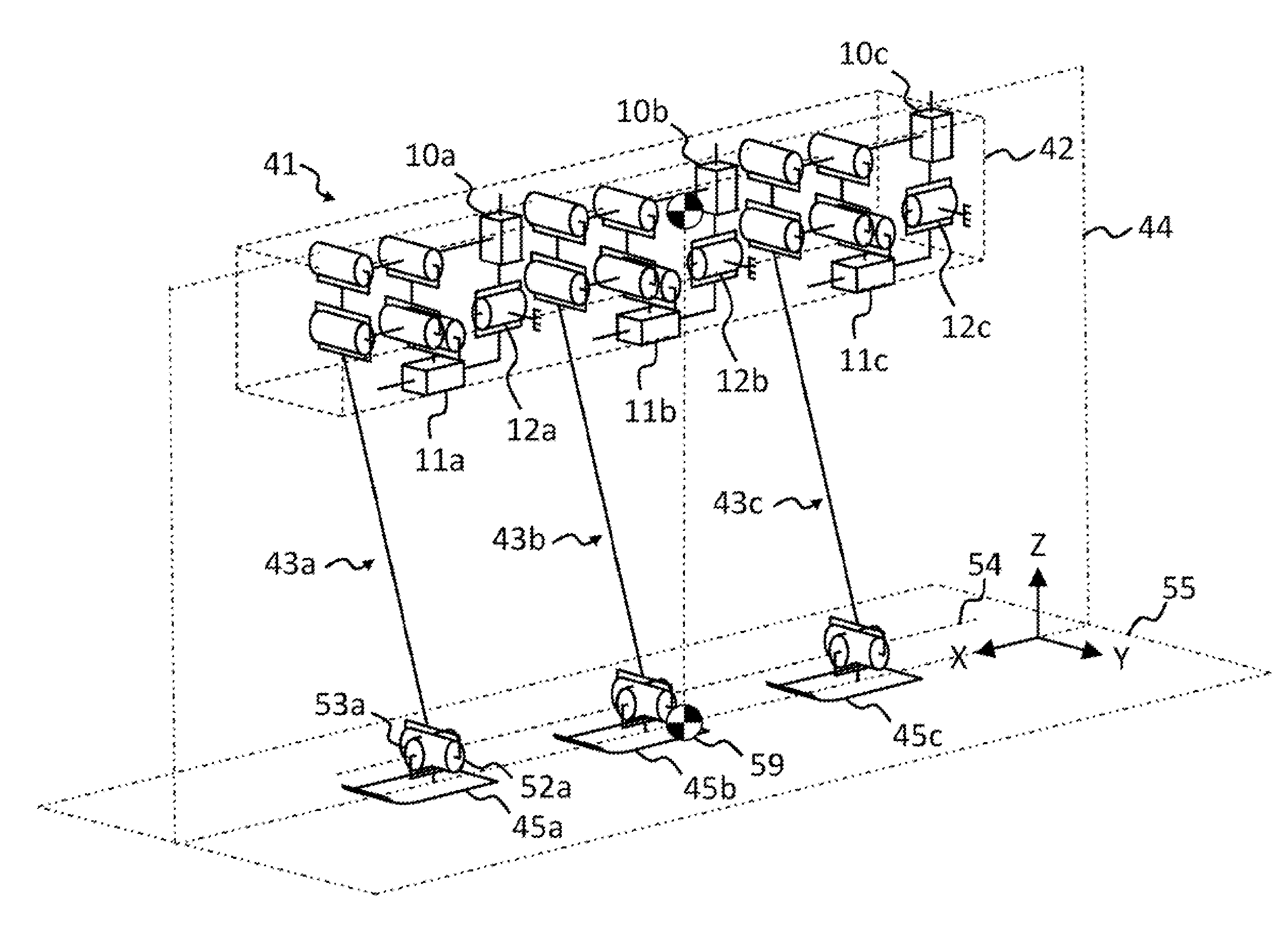
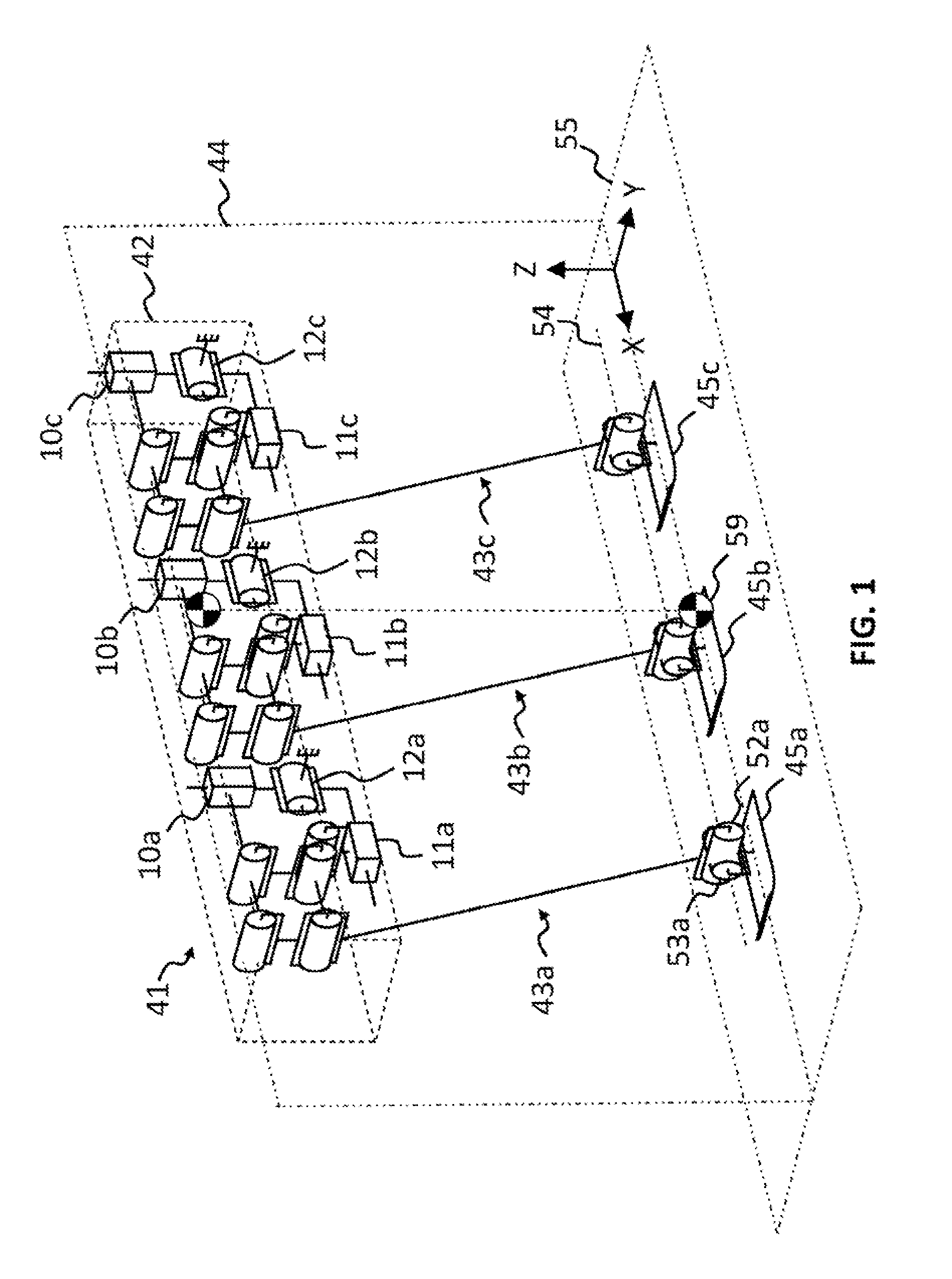
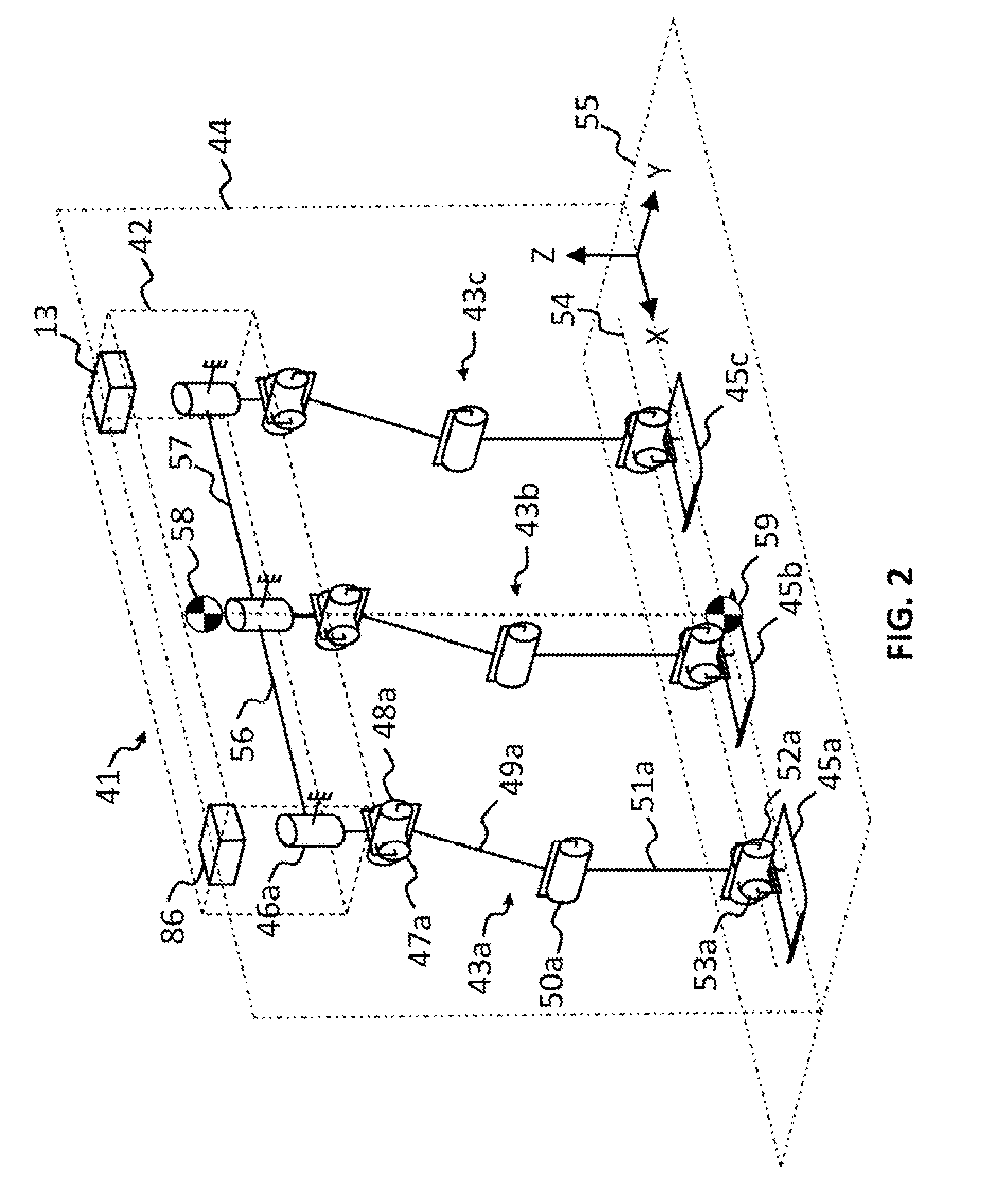
The invention will now be explained with reference to a single track or in-line three legged mobile robot as a specific embodiment of the single track multi-legged mobile robot. Referring now to the drawings and, more particularly, to FIGS. 1-3 thereof, there is shown a single track or in-line legged mobile robot, generally designated 41, including a body or frame, generally designated 42, and three identical leg mechanisms, generally designated 43, attached one behind the other, substantially parallel to the major axis of the frame 42, defining a forward / backward direction of travel along planes 44 and 55. By convention, the left side of the page is the front side and forward direction, the right side of the page is the rear side, into the page is the right side, and out of the page is the left side of the robot 41. The construction of each leg mechanism 43 is not directly relevant to the present invention, the present invention being directed to the method and manner in which the ...


PUM


Abstract

A legged vehicle includes a body, wherein the body includes a major axis corresponding to a primary direction of travel; a plurality of leg mechanisms attached to the body, wherein each leg is attached at its proximal end at one or more discrete attachment points, wherein the attachment points are arranged in-line, one behind the other, with respect to the body, each of the legs including actuators attached between the legs and the body and between adjacent leg members, said legs being actuated for movement of a distal end in three dimensions; a control system in communication with the leg mechanisms to coordinate movements of the leg mechanisms according to approximately single track foot placement, and movement of the legged vehicle in three dimensions over the ground; and a power source connected to and driving the control system components and the plurality of actuators and joints which drive the legs.

Description

CROSS-REFERENCE TO RELATED APPLICATIONSNot ApplicableSTATEMENT REGARDING FEDERALLY SPONSORED RESEARCH OR DEVELOPMENTNot ApplicableREFERENCE TO SEQUENCE LISTING, A TABLE, OR A COMPUTER PROGRAM LISTING COMPACT DISK APPENDIXNot ApplicableFIELD OF THE INVENTIONThe present invention relates to a legged mobile robot and, more particularly, to a legged mobile robot having a plurality of legs arranged in a narrow profile to walk and maneuver along paths by placing successive footfalls in a generally single-track or in-line fashion. Furthermore, the invention relates to an automatic system for sensing and preventing turnover of single-track legged mobile robots while enabling normal riding techniques in all but out of control situations.BACKGROUND OF THE INVENTIONPrior-art legged vehicles, especially those adapted for moving over rough or uneven terrain have been proposed. The terms vehicle, walking machine, and robot are to be construed broadly and includes any means of transportation, whet...

Claims


Application Information

Patent Timeline
Patent Type & Authority Applications(United States)
IPC IPC(8): G05D1/00B62D57/032G16Z99/00
CPCB62D57/024B62D57/032Y10S901/01B25J9/1633B25J5/00G16Z99/00B25J9/16B25J19/00B62D57/00B25J9/1674B62D57/02G01C21/26G05D1/0088G05D1/0891
Inventor GOULDING, JOHN R.
Owner GOULDING JOHN R
Learn More