
Fuel Nozzle

a fuel nozzle and fuel technology, applied in the field of fuel nozzles, can solve the problems of poor nox value and unfavorable drop, and achieve the effects of improving improving the mixing of fuel, and increasing the flow velocity of fuel

Inactive Publication Date: 2011-09-29
SIEMENS AG
View PDF17 Cites 11 Cited by
  • Summary
  • Abstract
  • Description
  • Claims
  • Application Information

AI Technical Summary

Benefits of technology

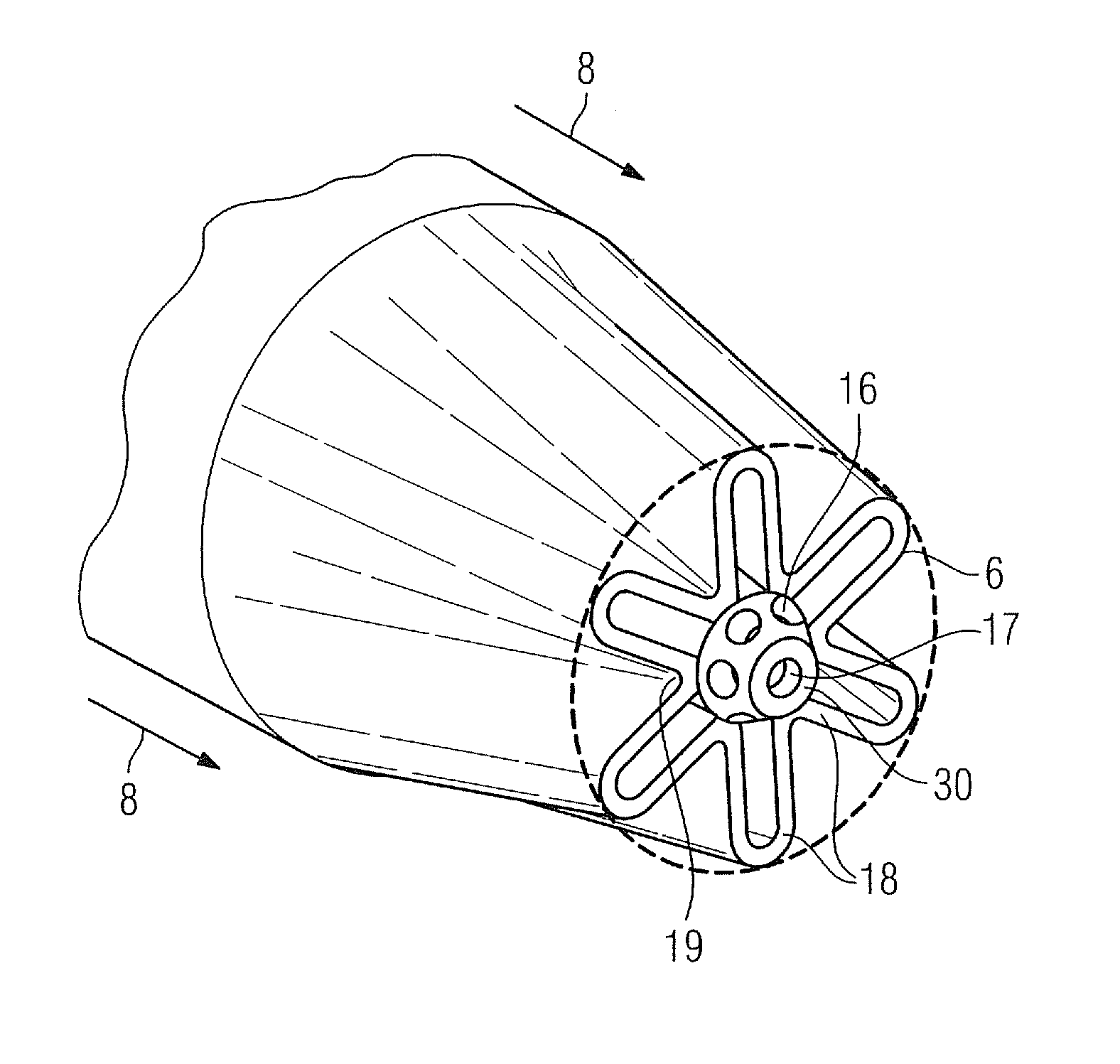
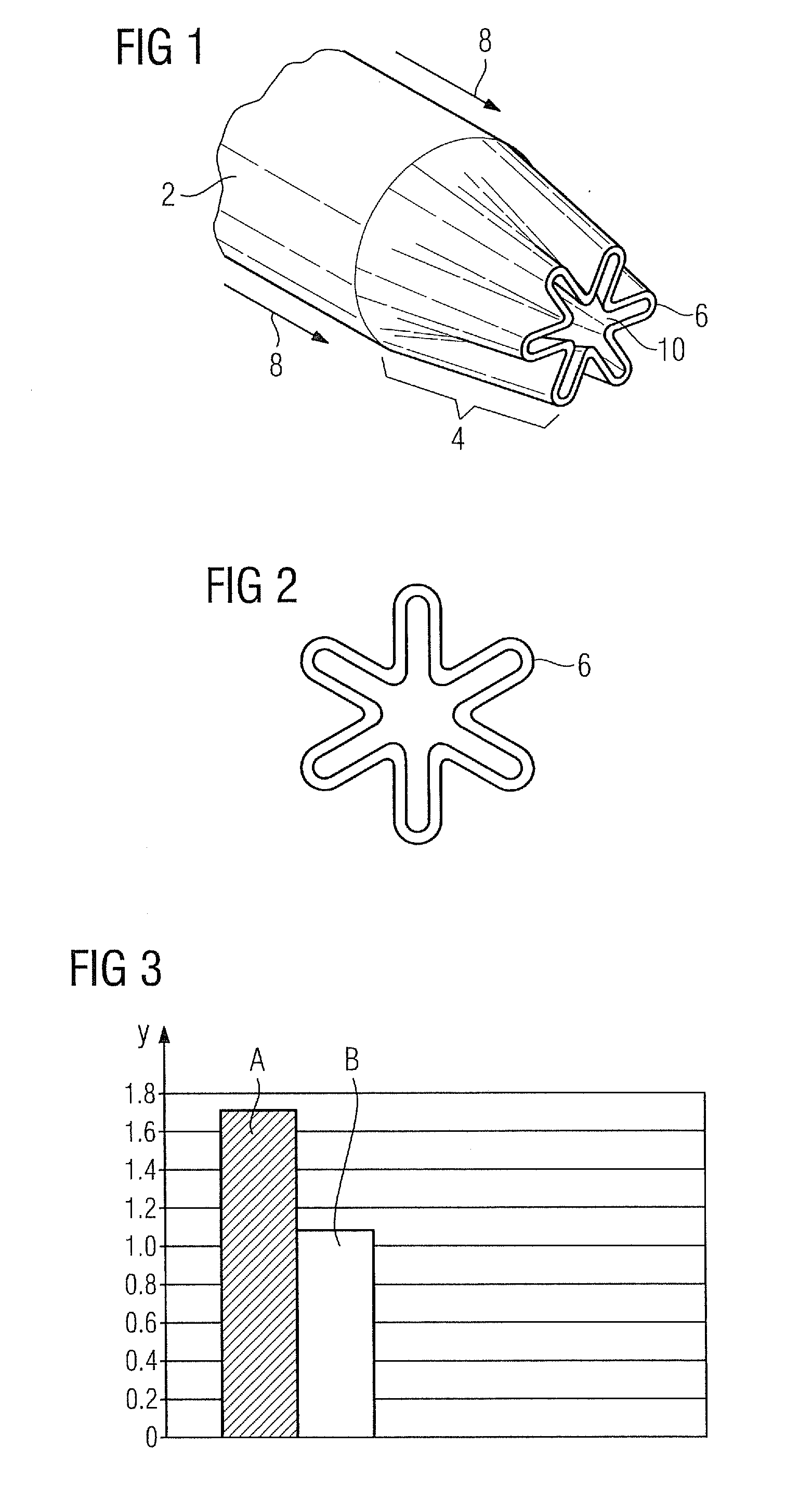
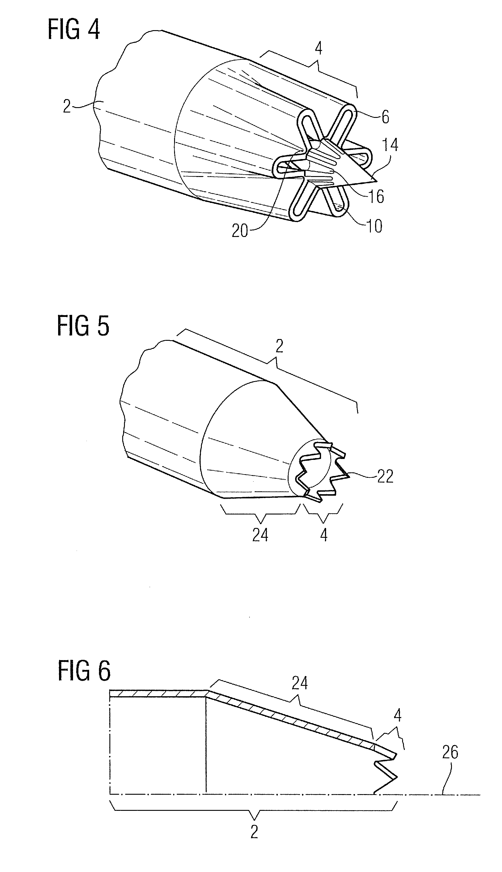
[0017]In this case the invention proceeds on the basis of the knowledge that an increase in the size of the contact area between synthesis gas flow and air flow produces a substantial improvement in the mixing process. This effect is crucial in particular when the fuel flow and the air flow have different flow velocities. This is brought about by the embodiment of the first nozzle tube section in the shape of a flower. Furthermore, the flower-shaped embodiment of the first nozzle tube section causes a second flow field, i.e. desired calculable turbulations, to faun at the profile trailing edges, which in turn improves the thoroughness of the mixing. This, too, is advantageous in particular when the fuel flow and the air flow have different flow velocities. The inventive flower-shaped embodiment of the first nozzle tube section furthermore enables a coaxial injection of the fuel into the air flow. By this means undesirably high drops in pressure are avoided. This permits the nozzle to be operated in the premix mode, even with high volumetric flow rates of fuel, as is the case e.g. with synthesis gas.
[0029]It should be noted here that both the inlet openings for high-calorie fuel and the feed itself only require a small diameter, since the volumetric flow rate of the high-calorie fuel is significantly less than that of the synthesis gas. This is a contributory factor helping to ensure the feed for high-calorie fuel causes no or only minor disturbance in the air flow during synthesis gas operation.

Problems solved by technology

However, the swirling elements used in the prior art and the injection of the fuel flow transversely with respect to the air flow lead to a considerable undesired drop in pressure which in turn leads to poor NOx values.

Method used


Image

  • Fuel Nozzle
  • Fuel Nozzle
  • Fuel Nozzle

Examples


Embodiment Construction

[0042]The high cost of natural gas is causing the current development of gas turbines to be driven in the direction of alternative fuels such as synthesis gas, for example. In principle, synthesis gas can be produced from solid, liquid or gaseous starting materials. Coal gasification should be cited as the principal method for producing synthesis gas from solid starting materials. With this process, coal is converted in a mix consisting of partial oxidation and gasification with water vapor into a mixture of CO and hydrogen. Basically, the use of other solid materials such as e.g. biomass and coke should also be mentioned in addition to coal. Different crude oil distillates can be used as liquid starting materials for synthesis gas, while natural gas should be cited as the most important gaseous starting material. In this context it should, however, be noted that the low calorific value in the case of synthesis gas means that significantly higher volumetric flows must be fed to the ...


PUM


Abstract

A fuel nozzle including a nozzle tube and a nozzle outlet opening is provided. The nozzle tube is connected to a fuel feed line for feeding a fuel to the nozzle tube, wherein the fuel is fed from the nozzle outlet opening to an annular air stream surrounding the fuel nozzle, wherein a first nozzle tube section that extends up to the nozzle outlet opening is designed in a floral pattern in such a way that the fuel may be fed substantially coaxially into the air stream.

Description

CROSS REFERENCE TO RELATED APPLICATIONS[0001]This application is the US National Stage of International Application No. PCT / EP2009 / 062460, filed Sep. 25, 2009 and claims the benefit thereof. The International Application claims the benefits of European Patent applications No. 08017127.5 EP filed Sep. 29, 2008 and No. 08017128.3 EP filed Sep. 29, 2008. All of the applications are incorporated by reference herein in their entirety.FIELD OF INVENTION[0002]The invention relates to a fuel nozzle comprising a nozzle tube and a nozzle outlet opening, wherein the nozzle tube is connected to a fuel feed line for the purpose of feeding a fuel into the nozzle tube, wherein the fuel is injected from the nozzle outlet opening into an air flow which surrounds the fuel nozzle essentially in a ring shape, and a first nozzle tube section extending as far as the nozzle outlet opening is embodied in a flower shape and moreover in such a way that the fuel can be injected essentially coaxially into the ...

Claims


Application Information

Patent Timeline
IPC IPC(8): F23D14/22F23D14/58F23R3/28
CPCF23D14/22F23R3/28F23D14/58
Inventor COLMEGNA, GIACOMOWORZ, ULRICHVAN KAMPEN, JAAP
Owner SIEMENS AG
Learn More