

Marine vessel provided with vertically arranged revolving cylinders
- Summary
- Abstract
- Description
- Claims
- Application Information
AI Technical Summary
Benefits of technology
Problems solved by technology
Method used
Image

Examples
Embodiment Construction
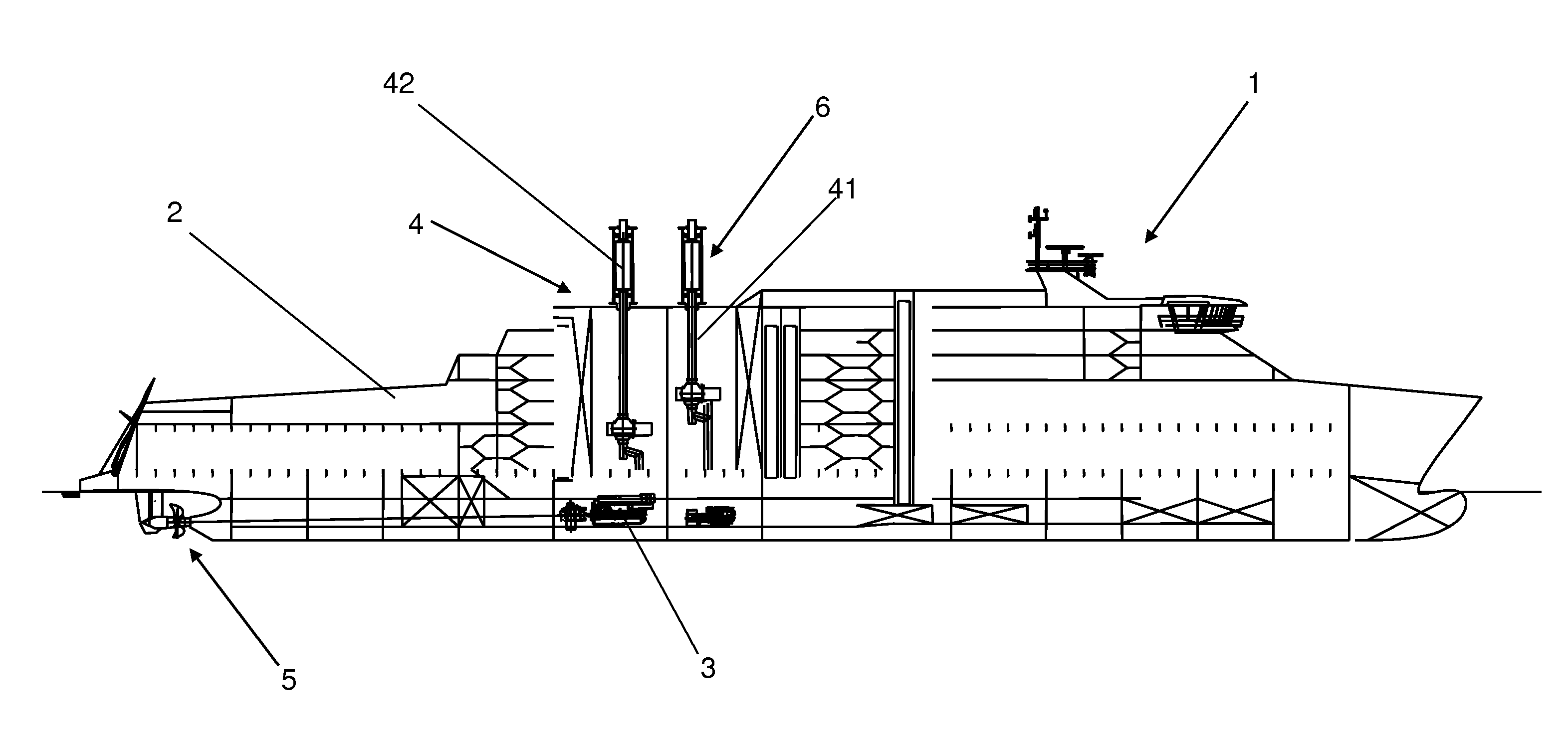
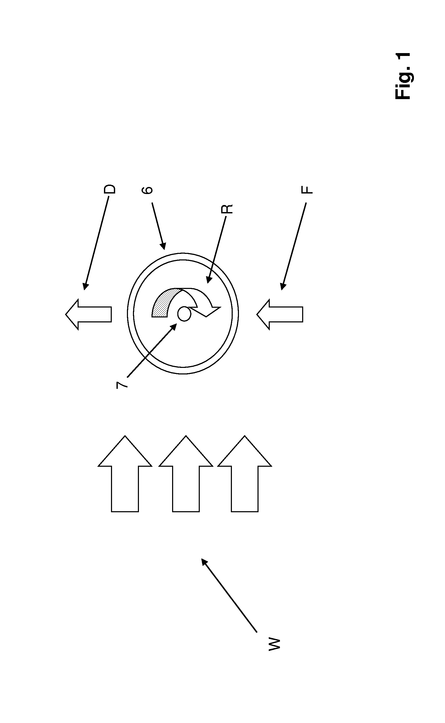
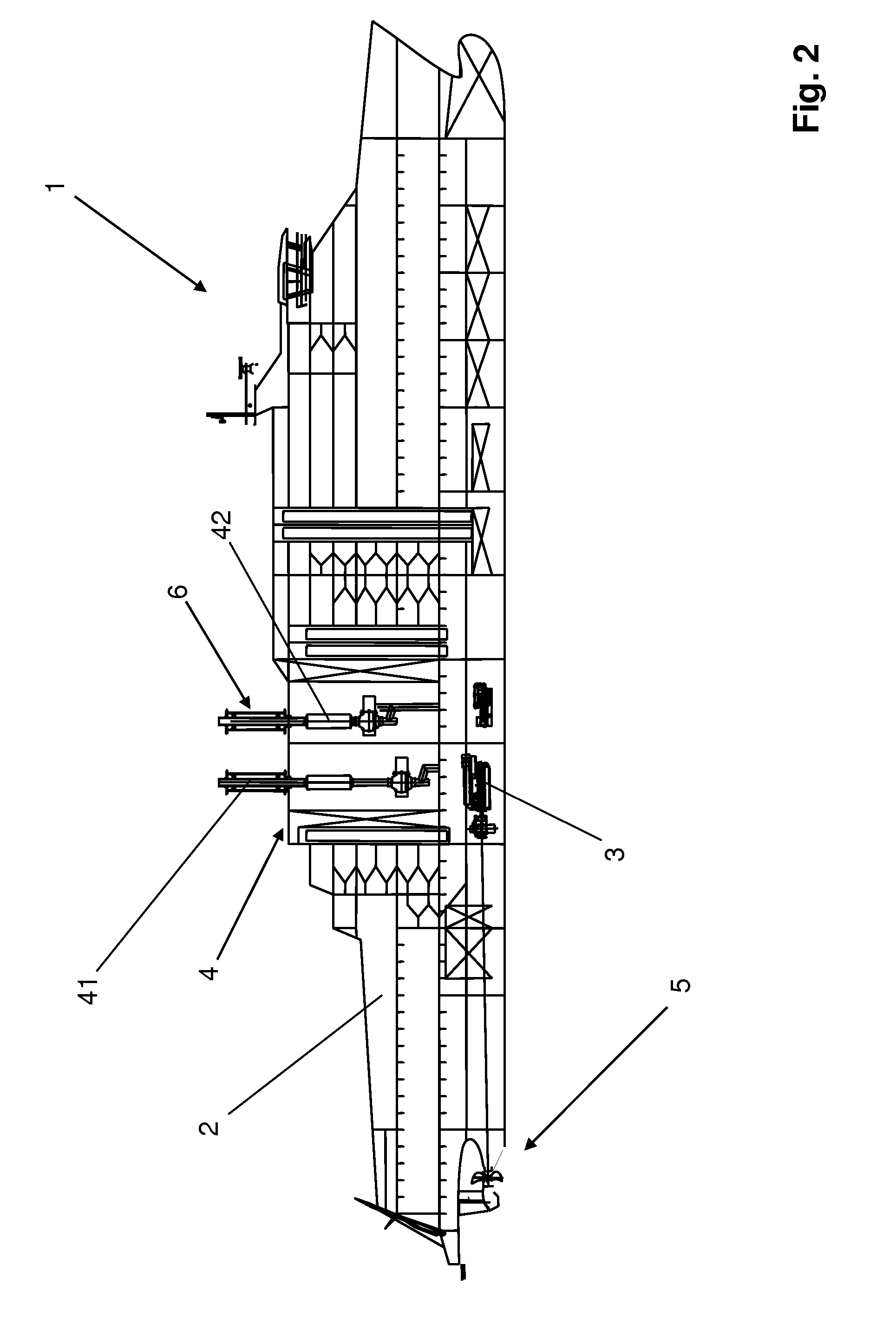
[0022]FIG. 1 illustrates the general principle of the present invention. The vertically arranged cylinder is indicated by reference sign 6 and its vertical axis by reference sign 7. The three parallel arrows show the wind indicated by reference sign W, the curved arrow R indicates the direction of rotation of the vertically arranged cylinder 6 around its vertical axis 7, reference sign F indicates the force, or forward thrust, generated by the Magnus effect discussed above, and reference sign D indicates the resulting direction of movement of the marine vessel (not shown).
[0023]The side wind W engages the vertically arranged cylinder 6 which is rotated around its vertical axis 7 by means of a motor (not shown) in direction R, whereby the Magnus effect generates an increased pressure on one side and an decreased pressure, or suction, at the opposite side of the vertically arranged cylinder 6. This results in a force F, or forward thrust, which moves the marine vessel forward in direc...
PUM
 Abstract
Description
Claims
Application Information