Diaphragm, diaphragm valve, and method of manufacturing diaphragm

a manufacturing method and diaphragm technology, applied in the direction of diaphragm valves, engine diaphragms, functional valve types, etc., can solve the problems of reducing the durability of the diaphragm valve, difficult to increase the displacement amount of the metal diaphragm, and increasing the stress applied to the metal diaphragm, etc., to achieve high long-term durability, high hardness and tensile strength, and effective reduction of stress applied

Active Publication Date: 2011-09-29
SEIKO INSTR INC
View PDF11 Cites 10 Cited by
  • Summary
  • Abstract
  • Description
  • Claims
  • Application Information

AI Technical Summary

Benefits of technology

[0020]The diaphragm of the present invention can effectively reduce the stress applied to the diaphragm by setting the radius of curvature R of the boundary portion positioned at the border between the dome portion and the flange portion in a predetermined range on the convex side of the dome portion. Thus, even in the case of increasing the Cv value by increasing the displacement amount of the diaphragm, high long-term durability can be obtained. Further, the diaphragm of the present invention is formed of the cobalt-based superalloy or nickel-based superalloy with a predetermined composition, and thus, the diaphragm can have high hardness and tensile strength, long life even used under a high pressure, and high corrosion resistance which enables the diaphragm to be used even for corrosive gas.
[0021]The diaphragm valve of the present invention includes the diaphragm of the present invention having the above-mentioned excellent characteristics, and hence has high strength, corrosion resistance, and long-term durability.
[0022]Further, according to the method of manufacturing a diaphragm of the present invention, the diaphragm having high strength, corrosion resistance, and long-term durability can be provided.

Problems solved by technology

Further, because the metal diaphragm is used repeatedly at a high frequency as an open / close valve for corrosive gas, the metal diaphragm is required to have durability under such a severe use environment.
However, when the displacement amount of the metal diaphragm is increased, the stress applied to the metal diaphragm is increased, which reduces the durability of the diaphragm valve.
Therefore, it has been difficult to increase the displacement amount of the metal diaphragm while maintaining durability.

Method used


Image

  • Diaphragm, diaphragm valve, and method of manufacturing diaphragm
  • Diaphragm, diaphragm valve, and method of manufacturing diaphragm
  • Diaphragm, diaphragm valve, and method of manufacturing diaphragm

Examples


example 1

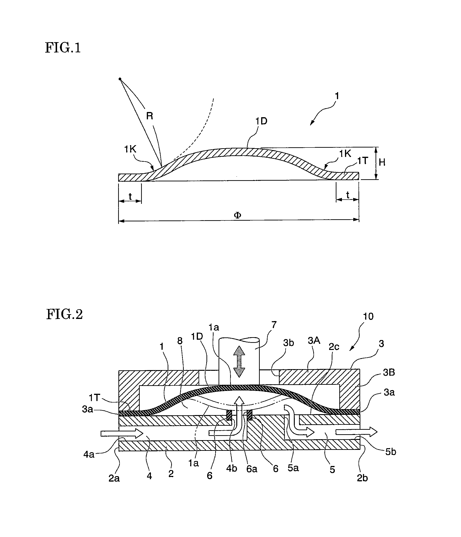
[0067]An alloy having a composition of Cr:20.11%, Ni:32.07%, Mo:10.02%, Fe:1.9%, Nb:0.91%, Mn:0.2%, Ti:0.49%, C:0.014%, and Si:0.04% in terms of mass ratio, with the remaining part being formed of Co and inevitable impurities, was ultra-cleaned by vacuum melting, and the resultant alloy was subjected to cold working with a working ratio of 80% to manufacture a bar with a thickness of 0.1 mm. After the bar was die-cut to a disk shape by punching, the bar was molded in a dome shape. Thus, a plurality of diaphragms in a shape illustrated in FIG. 1 having an outer diameter Φ of 20 mm, a thickness of 0.1 mm, a height H of 0.75 mm, and a width t of a flange portion of 1 mm were manufactured with R being set to respective values of 0.6 mm, 1.2 mm, 2.5 mm, 4.0 mm, and 5.7 mm.

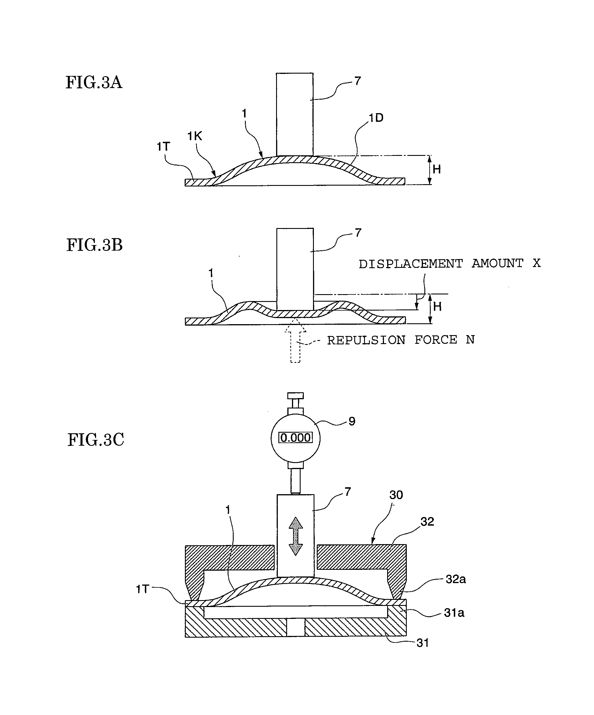
[0068]A relationship of a repulsion force with respect to a displacement amount that is a deformation degree of the diaphragm was measured on each manufactured diaphragm. A measurement method is described with reference...

example 2

[0074]A plurality of diaphragms having an outer diameter Φ of 15 mm, a thickness of 0.1 mm, a height H of 0.50 mm, and a width t of a flange portion of 1 mm, with a radius of curvature R being set to 0.5 to 6.7 mm, were manufactured in the same way as in Example 1. For each of the obtained diaphragms having an outer diameter Φ of 15 mm, a relationship between the maximum repulsion force and the radius of curvature R was obtained in the same way as in Example 1, except for changing the outer diameter of the stem to 6 mm. FIG. 5A shows the results.

[0075]As illustrated in FIG. 5A, even in the diaphragm having the outer diameter Φ of 15 mm, the maximum repulsion force was reduced as the radius of curvature R was increased. The upper limit value (R0 value) of the radius of curvature R at which a repulsion force (stress) applied to the diaphragm can be reduced effectively, and the value (R1 value) of the radius of curvature R at which a high stress reducing effect is obtained were obtaine...

example 3

[0076]A plurality of diaphragms having an outer diameter Φ of 26 mm, a thickness of 0.1 mm, a height H of 0.95 mm, and a width t of a flange portion of 1 mm, with a radius of curvature R being set to 0.5 to 6.1 mm, were manufactured in the same way as in Example 1. For each of the obtained diaphragms having an outer diameter Φ of 26 mm, a relationship between the maximum repulsion force and the radius of curvature R was obtained in the same way as in Example 1, except for changing the outer diameter of the stem to 10 mm. FIG. 5B shows the results.

[0077]As illustrated in FIG. 5B, even in the diaphragm having the outer diameter Φ of 26 mm, the maximum repulsion force was reduced as the radius of curvature R was increased. The upper limit value (R0 value) of the radius of curvature R at which a repulsion force (stress) applied to the diaphragm can be reduced effectively, and the value (R1 value) of the radius of curvature R at which a high stress reducing effect is obtained were obtain...


PUM

PropertyMeasurementUnit
outer diameteraaaaaaaaaa

Abstract

Provided are a diaphragm, a diaphragm valve, and a method of manufacturing a diaphragm capable of increasing a flow rate (Cv value) of gas without degrading long-term durability even when a displacement amount is increased. A diaphragm (1) has an outer diameter Φ of 10 to 35 mm and includes a dome portion (1D) in a dome shape and a flange portion (1T) formed continuously at a peripheral edge of the dome portion (1D) via a boundary portion (1K), the boundary portion (1K) has a radius of curvature R of 0.6 mm or more on a convex side of the dome portion (1D), and the diaphragm is formed of a cobalt-based super-alloy.

Description

RELATED APPLICATIONS[0001]This application claims priority under 35 U.S.C. §119 to Japanese Patent Application No. 2010-067974 filed on Mar. 24, 2010, the entire content of which is hereby incorporated by reference.BACKGROUND OF THE INVENTION[0002]1. Field of the Invention[0003]The present invention relates to a diaphragm, a diaphragm valve, and a method of manufacturing a diaphragm.[0004]2. Description of the Related Art[0005]In a semiconductor manufacturing gas process or the like in which highly corrosive gas is used, a diaphragm valve that functions as an open / close valve for the corrosive gas is required to have high corrosion resistance. Therefore, conventionally, as a diaphragm of high performance used in a semiconductor manufacturing gas process or the like, a metal diaphragm made of a superalloy of a cobalt group, a nickel group, etc. is used.[0006]Further, a diaphragm valve used for the above-mentioned application is required to have strength that enables baking in a low t...

Claims


Application Information

Patent Timeline
Patent Type & Authority Applications(United States)
IPC IPC(8): F16K7/12B21D35/00
CPCC22C19/055C22C19/056Y10T428/1241F16K7/14C22C19/07F16K7/12F16K7/16
Inventor KAMADA, TAKASHITAKAHASHI, KYOTARO
Owner SEIKO INSTR INC
Why Eureka
Try Eureka