

Motor control device and electrical equipment with motor controlled thereby
- Summary
- Abstract
- Description
- Claims
- Application Information
AI Technical Summary
Benefits of technology
Problems solved by technology
Method used
Image

Examples
Embodiment Construction
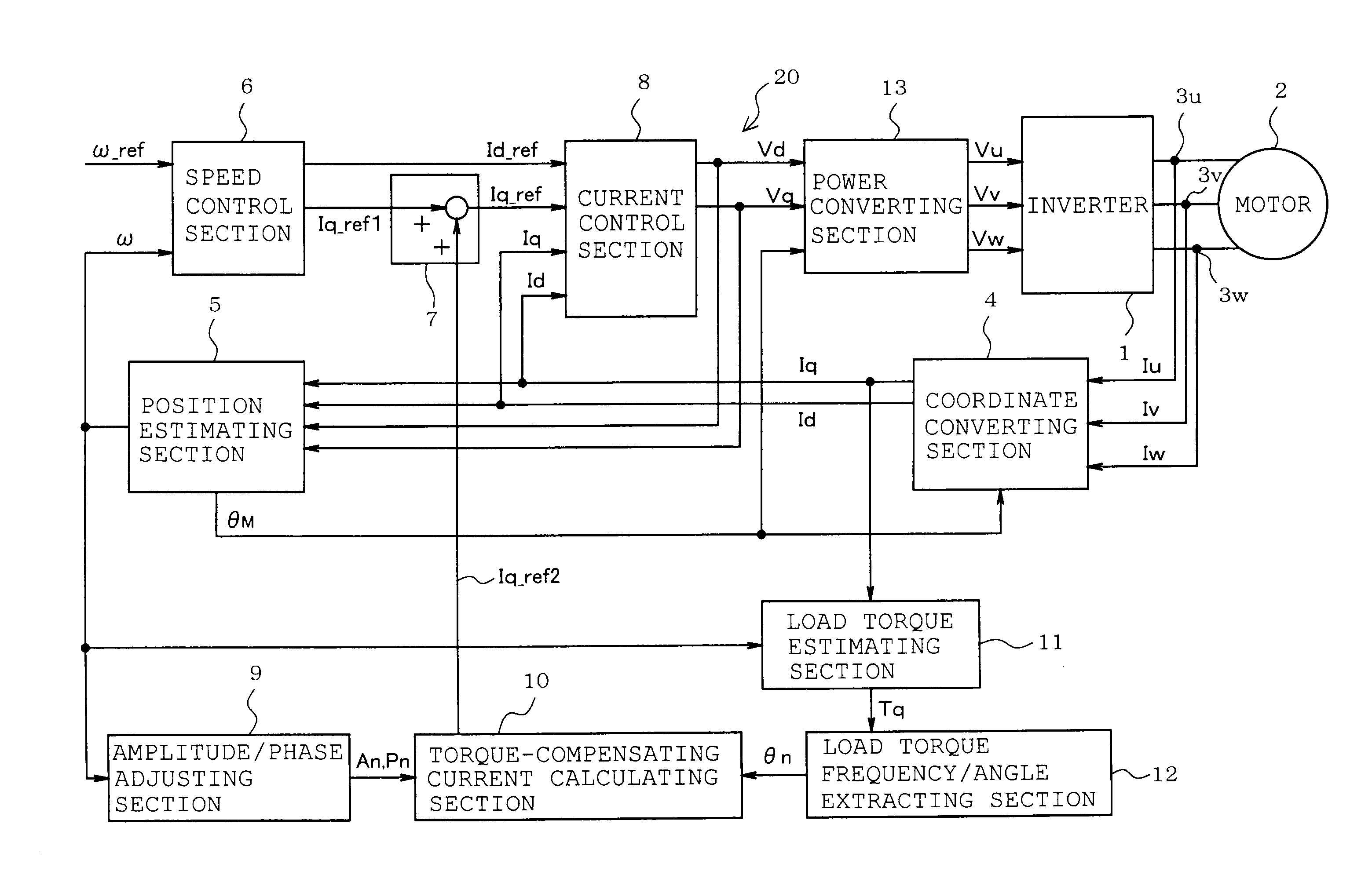
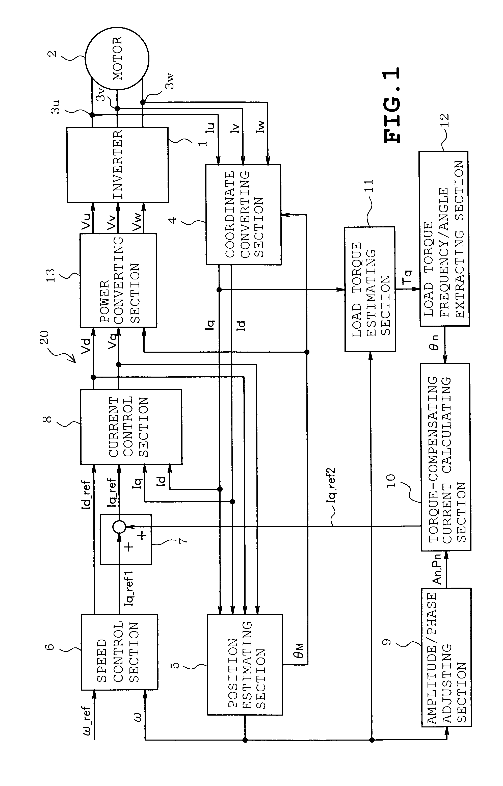
According to one embodiment, a motor control device comprises an electric power supply unit which supplies AC current to an electric motor driving a load; a current detecting unit which detects current flowing into a winding of the motor; a speed / electrical angle estimating unit which estimates a rotational speed and an electrical angle of the motor, based on the current detected by the current detecting unit; a load torque estimating unit which estimates a load torque to be produced by the load, from a torque current obtained based on the current detected by the current detecting unit and the electrical angle estimated by the speed / electrical angle estimating unit, a motor constant and inertia moment of the motor inclusive of the load; a load torque phase calculating unit which calculates a phase of periodic fluctuation indicated by the load torque; a torque-compensating current determining unit which determines a sinusoidal torque-compensating current, based on the load torque pha...
PUM
 Abstract
Description
Claims
Application Information