Eureka AIR delivers breakthrough ideas for toughest innovation challenges, trusted by R&D personnel around the world.

Method and Communication Network Element for Transmitting Reference Signals

a communication network and reference signal technology, applied in the field of communication network elements and methods of transmitting data, can solve the problems of large amount of data on the backbone network, inability to fully cooperate, and limiting the performance of data transmission known in the prior art, so as to minimize inter-cell crosstalk, improve multi-cell channel estimation, and design full flexibility

Active Publication Date: 2011-09-29
NOKIA TECHNOLOGLES OY
View PDF3 Cites 38 Cited by
  • Summary
  • Abstract
  • Description
  • Claims
  • Application Information

AI Technical Summary

Benefits of technology

[0016]By a method according to an exemplary aspect of he invention it may be possible to ensure a backward compatibility of a communication system relating to a new standard, e.g. it may be possible to combine a Release 8 standard with an LTE advanced standard by using two different types of reference signals wherein one type may be adapted to be used in Release 8 communication systems or transmission schemes while the other one may be adapted to be used in an advanced LTE standard. Each of the two reference signals may be a common reference signal, e.g. may be common for all channels. Since both types of reference signals may be specifically adapted to one standard it may be possible to ensure a high accuracy of the channel state estimation (CSI), which may even facilitate interference rejection combining (IRC) which may be seen as another significant ingredient of COOPA systems and which may rely as well on high quality CSI estimation.
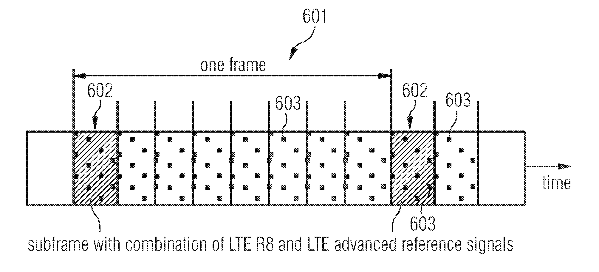
[0043]The other resource elements normally carrying R8 data signals may then be used for new CRSs for LTE Advanced. Specifically the application of Hadamard sequences for CRS of different cells might be applied, minimizing inter-cell crosstalk between reference signals from different cells. In a simple scheme specific subframes may carry a combination of LTE Release 8 CRS together with LTE Advanced reference signals at the other REs not occupied by R8 RSs. In that case Release 8 UEs may not see any of these newly defined reference signals as the eNBs simply do not schedule any Release 8 UEs in this specific subframe. The resulting additional overhead may be in the order of 10% (one out of 10 subframes). Furthermore, semistatically definition of other configurations with more or less subframes for LTE Advanced CRSs might be useful to adapt to different radio conditions.

Problems solved by technology

One problem limiting the performance of the data transmission known in the prior art is inter cell and intra cell interference.
At the same time it is clear that full cooperation is not practical due to required channel state information (CSI) to a huge number of base stations (BS) and accordingly large feedback overhead, especially in case of FDD systems.
A further topic is the large amount of data on the backbone network, which might generate a lot of costs in terms of CAPEX and OPEX.
This channel estimation may be a major challenge, especially due to the inter cell interference from a large number of cells and sites in mobile communication systems.

Method used


Image

  • Method and Communication Network Element for Transmitting Reference Signals
  • Method and Communication Network Element for Transmitting Reference Signals
  • Method and Communication Network Element for Transmitting Reference Signals

Examples


Embodiment Construction

[0052]The illustration in the drawing is schematically. Identical or similar elements are labeled with identical or similar reference signs.

[0053]In the following, referring to FIGS. 1 to 3, some basic principles of a method of transmitting data and communication network elements according to exemplary embodiments will be explained.

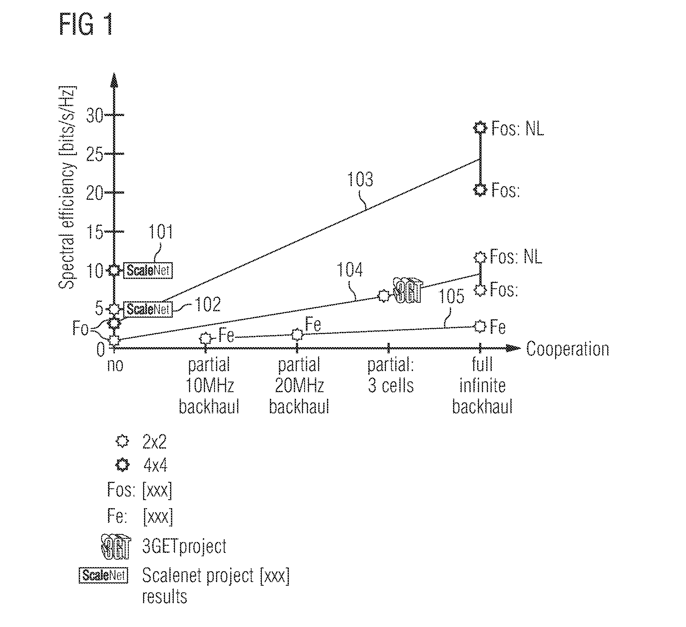
[0054]FIG. 1 schematically illustrates potential gains for different degrees of cooperation. That is, FIG. 1 shows the spectral efficiency in bits per seconds and hertz (bits / (s*Hz)) over different levels of cooperation. In particular, several schemes are depicted for several degrees of cooperation. The spectral efficiency for the “ScaleNet” results 101 and 102 represent the results for optimum MU-MIMO systems without cooperation but with full channel state information (CSI) knowledge. Furthermore, the “Fo” lines 103 and 104 represent the theoretical upper bounds for each level of cooperation, while the line “Fe”105 represents the results for a 5 MHz syst...


PUM


Abstract

A method of transmitting reference signals in a communication network from a first network element to a second network element is provided, wherein the method includes transmitting first type of reference signals using a first resource of a frame wherein the first type of reference signals are related to a first communication system, and transmitting second type of reference signals using a second resource of the frame wherein the second type of reference signals are related to a second communication system.

Description

FIELD OF INVENTION[0001]The present invention relates to the field of communication network elements and methods of transmitting data, in particular, in communication networks having cooperative antenna systems. Furthermore, the present invention relates to a communication network system, a program element and a computer readable medium.ART BACKGROUND[0002]Nowadays mobile communication networks are widely used. These communication networks comprise a plurality of network cells each having at least one base station used to receive and transmit signals from user equipment, e.g. mobile phones or PDAs. A plurality of different environments or systems is known, e.g. GERAN, UTRAN, LTE, E-UTRAN, WCDMA, or WLAN. For ensuring a good performance and in particular an effective data transmission it has to be ensured that all data, data signals, or data packets are received at the intended recipient and at possible relay stations, like base stations of the mobile communication network.[0003]One ...

Claims


Application Information

Patent Timeline
IPC IPC(8): H04W28/26H04W72/04
CPCH04L5/005H04L5/0048H04W72/04
Inventor HAUSTEIN, THOMASSCHULZ, EGONZIRWAS, WOLFGANG
Owner NOKIA TECHNOLOGLES OY
Why Eureka
Eureka Blog
Learn More