Guide tube for guiding endoscope or surgical tool in or into body cavity

a technology for guiding endoscopes and surgical tools, applied in the field of guide tubes, can solve the problems of difficult to open a path of insertion, difficult to find, and often encountered difficulties, and achieve the effect of suppressing diametric differences and simple construction

Inactive Publication Date: 2011-09-29
FUJIFILM CORP
View PDF1 Cites 31 Cited by
  • Summary
  • Abstract
  • Description
  • Claims
  • Application Information

AI Technical Summary

Benefits of technology

[0018]As described above, the present invention makes it possible to construct a guide tube of a reduced diameter for an endoscope or a surgical tool, which is simple in construction and yet capable of transformation from a flexible structure to a highly rigid structure or vice versa in a secure and reliable manner, by incorporating muscle member into a flexible double tube, which is composed of inner and outer tubes, in such a way as to suppress a diametric difference between the inner and outer tubes.

Problems solved by technology

Therefore, in some cases, it is found extremely difficult to open a path of insertion in such a way as to ensure smooth introduction of an insertion rod of an endoscope for a treatment in an endoscopic operation.
Particularly, in case the insertion rod of the endoscope has a flexible structure, difficulties are often encountered in passing the insertion rod along a path of insertion opened up by perforation and in keeping the insertion rod in a stabilized state after insertion into a target intracavitary site to conduct a precision treatment in an appropriate manner.
The variable rigidity tube of Japanese Laid-Open Patent Application 2005-318956, which is composed of a series of successively connected ring members, has a disadvantage in that it requires a large number of parts.
Besides, the provision of axial grooves and ribs of predetermined height and depth on both of the inner and outer tubes invariably results in a variable rigidity tube which is unduly large in thickness and diameter.

Method used


Image

  • Guide tube for guiding endoscope or surgical tool in or into body cavity
  • Guide tube for guiding endoscope or surgical tool in or into body cavity
  • Guide tube for guiding endoscope or surgical tool in or into body cavity

Examples


Embodiment Construction

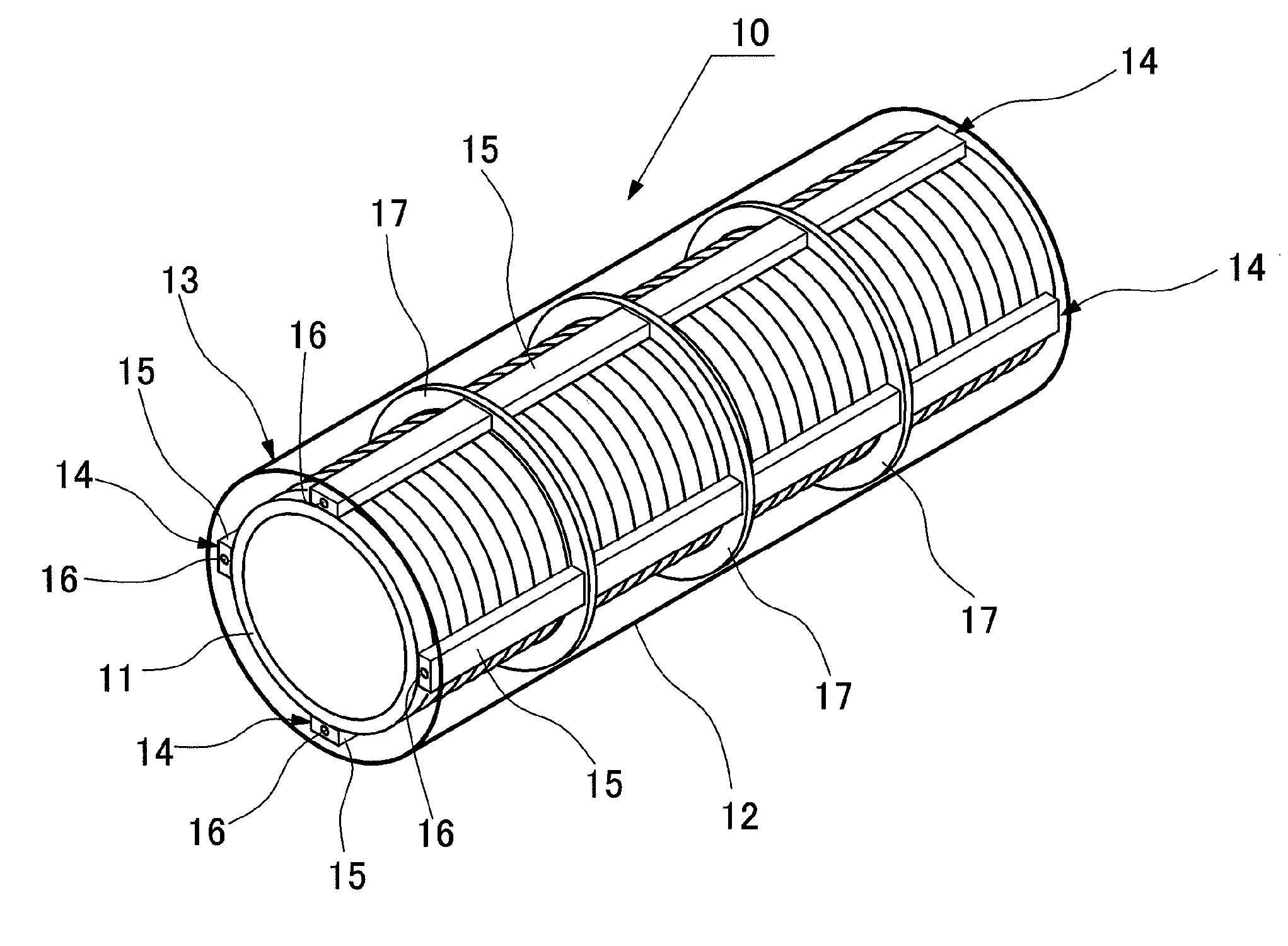
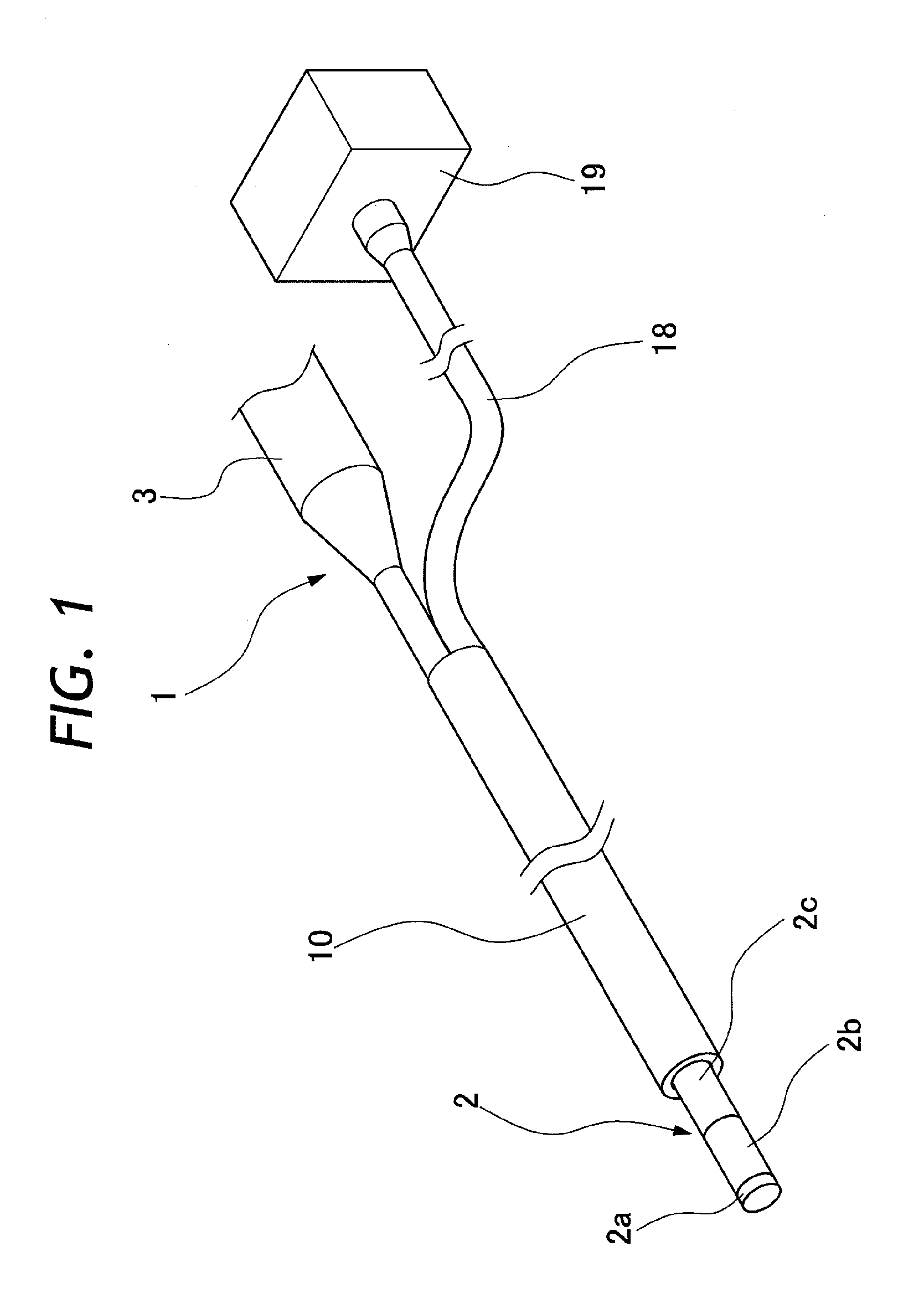
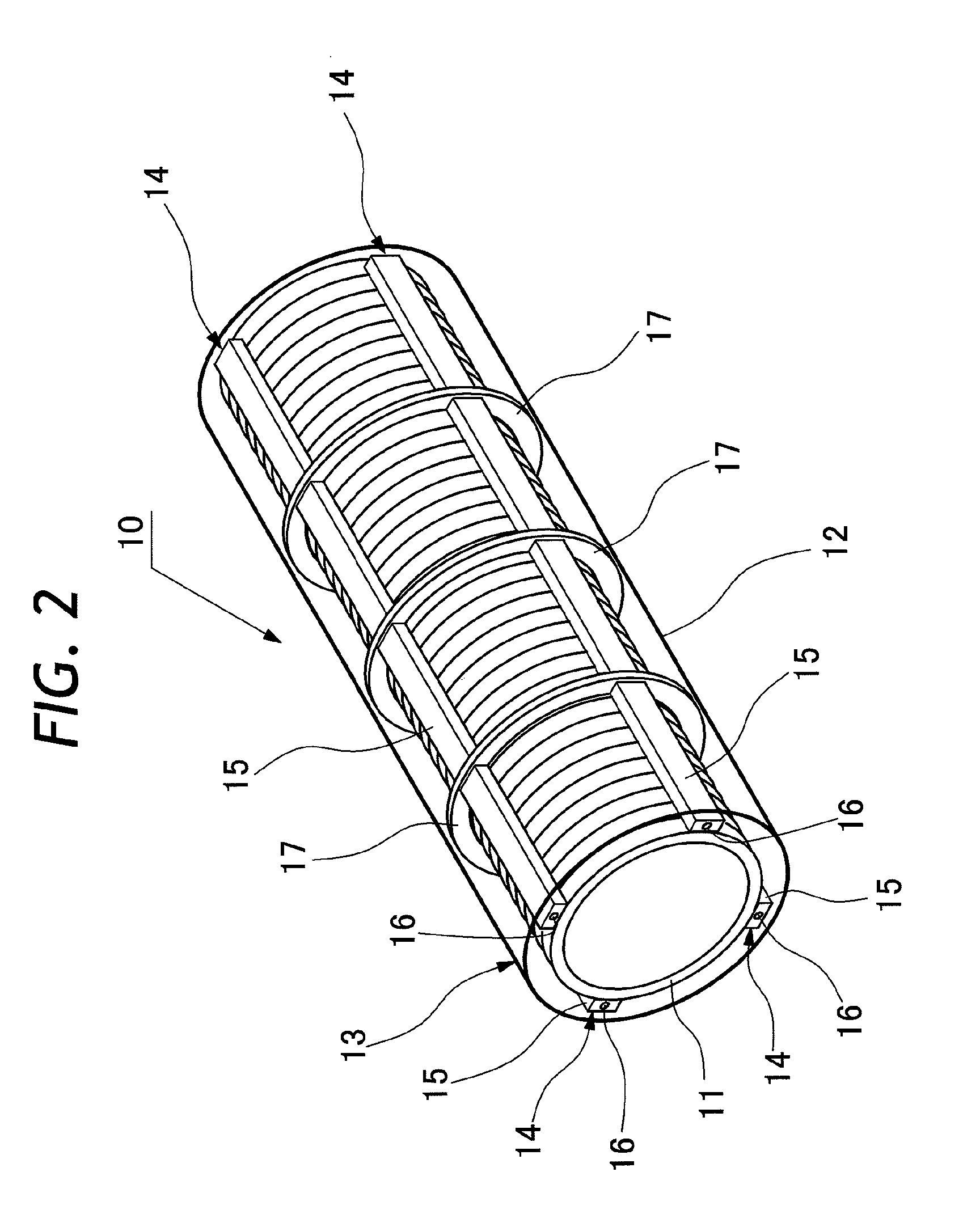
[0030]Hereafter, the present invention is described more particularly by way of its preferred embodiments. Needless to say, the present invention should not be construed as being limited to the particular embodiments shown. Referring first to FIG. 1, there is shown an outer view of a guide tube which is fitted on an endoscope. In FIG. 1, indicated at 1 is an endoscope having an elongated insertion rod 2 extended forward from a manipulating head grip 3 for insertion into a body cavity of a patient or examinee. From a fore distal end, the insertion rod 2 is composed of a rigid tip end section 2a, an articularly bendable section 2b, and an elongated flexible body section 2c. The flexible body section 2c of the insertion rod 2 is flexible in bending directions. Provided on the rigid tip end section 2a are an illumination light projection means to illuminate an intracavitary site of interest, and an observation window to capture picture images of the intracavitary site under illumination...


PUM


Abstract

In order to secure a path of insertion for an insertion rod 2 of an endoscope 1 and for transformation from a flexible structure to a rigid structure, a guide tube is constituted by a flexible double tube 13 having flexible inner and outer tubes 11 and 12 which are flexible in bending directions and fitted one on the other to define a hermetically closed space therebetween. Muscle members 14, each composed of a friction strip 15 and attached with a metal wire 16, are provided at predetermined angular positions between the inner and outer tubes. Dislodgements of the muscle members 14 from the respective angular positions are prevented by restraint rings 17. A suction tube 18 of a pump unit 19 is connected to the double tube 13 to evacuate a fluid from the closed space between the inner and outer tubes 11 and 12.

Description

FIELD OF THE INVENTION[0001]This invention relates to a guide tube suitable for use in endoscopy for stably guiding an endoscope or a surgical tool or the like in or into a body cavity of a patient or examinee.BACKGROUND OF THE INVENTION[0002]Normally, an endoscope is introduced into a patient along a path of insertion like an upper or lower digestive tract. As shown in Japanese Laid-Open Patent Application 2008-502421, for example, there is a technique of stomach perforation for bypassing an insertion rod of an endoscope from the stomach to the transverse colon of the large intestine. In such a case, it is important to suppress the invasive attacks to a minimum. Therefore, in some cases, it is found extremely difficult to open a path of insertion in such a way as to ensure smooth introduction of an insertion rod of an endoscope for a treatment in an endoscopic operation.[0003]Particularly, in case the insertion rod of the endoscope has a flexible structure, difficulties are often e...

Claims


Application Information

Patent Timeline
Patent Type & Authority Applications(United States)
IPC IPC(8): A61B1/00
CPCA61B1/00154A61B1/0051A61B1/00078A61B1/12A61B1/01
Inventor MATSUSHITA, MOTOHIKO
Owner FUJIFILM CORP
Why Eureka
Try Eureka