Data Reorganization through Hardware-Supported Intermediate Addresses

a technology of data reorganization and hardware support, applied in the field of memory systems, can solve the problems of cache hit and cache miss, and achieve the effect of improving the performance and efficiency of memory access and more efficient caching/access

Inactive Publication Date: 2011-09-29
IBM CORP
View PDF1 Cites 16 Cited by
  • Summary
  • Abstract
  • Description
  • Claims
  • Application Information

AI Technical Summary

Benefits of technology

[0006]The present invention provides a virtual address scheme for improving performance and efficiency of memory accesses of sparsely-stored data items in a cached memory system. In a preferred embodiment of the present invention, a special address translation unit is used to translate sets of non-contiguous addresses in real memory into contiguous blocks of addresses in an “intermediate address space.” This intermediate address space is a fictitious or “virtual” address space, but is distinguishable from the effective address space visible to application programs, and in user-level memory operations. Effective addresses seen and manipulated by application programs are translated into intermediate addresses by an additional address translation unit for memory caching purposes. This scheme allows non-contiguous data items in memory to be assembled into contiguous cache lines for more efficient caching / access (due to the perceived spatial proximity of the data from the perspective of the processor).

Problems solved by technology

Processors typically use caches to reduce the average time required to access memory, as cache memory is typically constructed of a faster (but more expensive or bulky) variety of memory (such as static random access memory or SRAM) than is used for main memory (such as dynamic random access memory or DRAM).
If the processor finds that the memory location is present in the cache, a cache hit has occurred.
Otherwise, a cache miss is present.

Method used


Image

  • Data Reorganization through Hardware-Supported Intermediate Addresses
  • Data Reorganization through Hardware-Supported Intermediate Addresses
  • Data Reorganization through Hardware-Supported Intermediate Addresses

Examples


Embodiment Construction

[0013]The following is intended to provide a detailed description of an example of the invention and should not be taken to be limiting of the invention itself. Rather, any number of variations may fall within the scope of the invention, which is defined in the claims following the description.

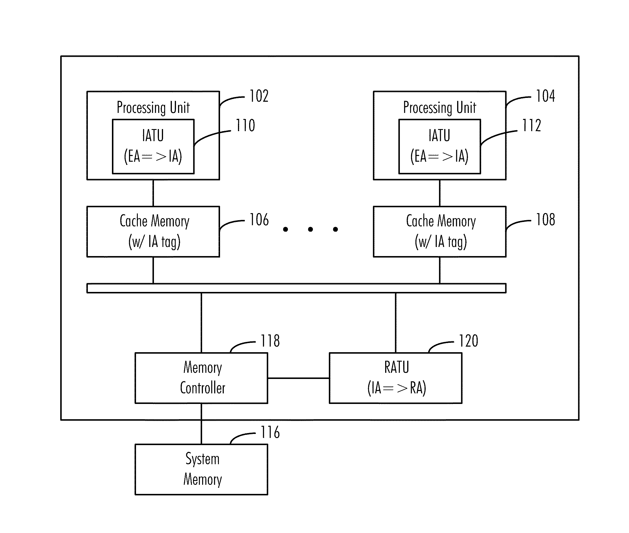
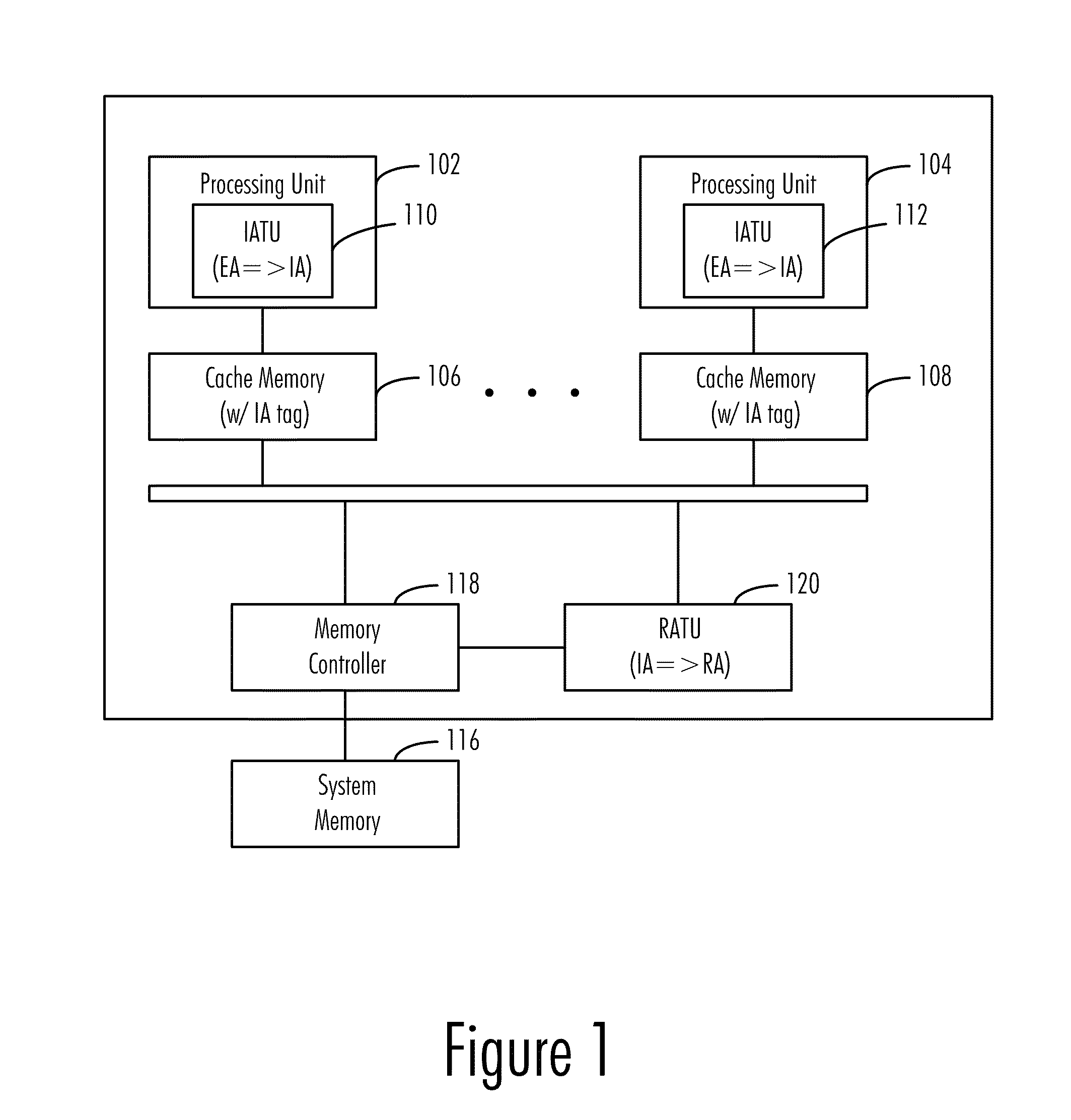
[0014]FIG. 1 is a block diagram of a data processing system 100 in accordance with a preferred embodiment of the present invention. Data processing system 100, here shown in a symmetric multiprocessor configuration (as will be recognized by the skilled artisan, other single-processor and multiprocessor arrangements are also possible), comprises a plurality of processing units 102 and 104, which provide the arithmetic, logic, and control-flow functionality to the machine and which share use of the main physical memory (116) of the machine through a common system bus 114. Processing units 102 and 104 may also contain one or more levels of on-board cache memory, as is common practice in present d...


PUM


Abstract

A virtual address scheme for improving performance and efficiency of memory accesses of sparsely-stored data items in a cached memory system is disclosed. In a preferred embodiment of the present invention, a special address translation unit is used to translate sets of non-contiguous addresses in real memory into contiguous blocks of addresses in an “intermediate address space.” This intermediate address space is a fictitious or “virtual” address space, but is distinguishable from the virtual address space visible to application programs, and in user-level memory operations, effective addresses seen/manipulated by application programs are translated into intermediate addresses by an additional address translation unit for memory caching purposes. This scheme allows non-contiguous data items in memory to be assembled into contiguous cache lines for more efficient caching/access (due to the perceived spatial proximity of the data from the perspective of the processor).

Description

BACKGROUND OF THE INVENTION[0001]1. Technical Field[0002]The present invention relates generally to memory systems, and more specifically to a memory system providing greater efficiency and performance in accessing sparsely stored data items.[0003]2. Description of the Related Art[0004]Many modern computer systems rely on caching as a means of improving memory performance. A cache is a section of memory used to store data that is used more frequently than those in storage locations that may take longer to access. Processors typically use caches to reduce the average time required to access memory, as cache memory is typically constructed of a faster (but more expensive or bulky) variety of memory (such as static random access memory or SRAM) than is used for main memory (such as dynamic random access memory or DRAM). When a processor wishes to read or write a location in main memory, the processor first checks to see whether that memory location is present in the cache. If the proce...

Claims


Application Information

Patent Timeline
Patent Type & Authority Applications(United States)
IPC IPC(8): G06F12/10
CPCG06F12/0207G06F12/1072G06F12/0864G06F12/0292
Inventor RAJAMONY, RAMAKRISHNANSPEIGHT, WILLIAM E.ZHANG, LIXIN
Owner IBM CORP
Why Eureka
Try Eureka