RF Screen Assembly for Microwave Powered UV Lamps

a technology of rf screen and uv lamp, which is applied in the field of microwave-powered uv lamp, can solve the problems of non-uniform mesh pattern, achieve the effects of enhancing light transmission in the preferred area of the screen, optimizing balance, and increasing flexibility

Active Publication Date: 2011-10-06
MILTEC
View PDF5 Cites 10 Cited by
  • Summary
  • Abstract
  • Description
  • Claims
  • Application Information

AI Technical Summary

Benefits of technology

[0010]Photo-chemically forming the mesh pattern in the RF screen provides increased flexibility to the manufacturer to form non-traditional (i.e., other than square or rectangular) mesh patterns. The screens of the present invention include individual openings of with 3 or more nodes. In one embodiment, the individual openings are polygonal and have 5 or more nodes. For instance, in some embodiments, the openings are hexagonal or octagonal in shape. Additionally, the manufacturer may select a mesh pattern that is non-uniform to enhance light transmission in preferred areas of the screen. The RF screen is generally configured to optimize the balance b...

Problems solved by technology

Additionally, the manufacturer may select a mesh pattern that is no...

Method used


Image

  • RF Screen Assembly for Microwave Powered UV Lamps
  • RF Screen Assembly for Microwave Powered UV Lamps
  • RF Screen Assembly for Microwave Powered UV Lamps

Examples


example 1

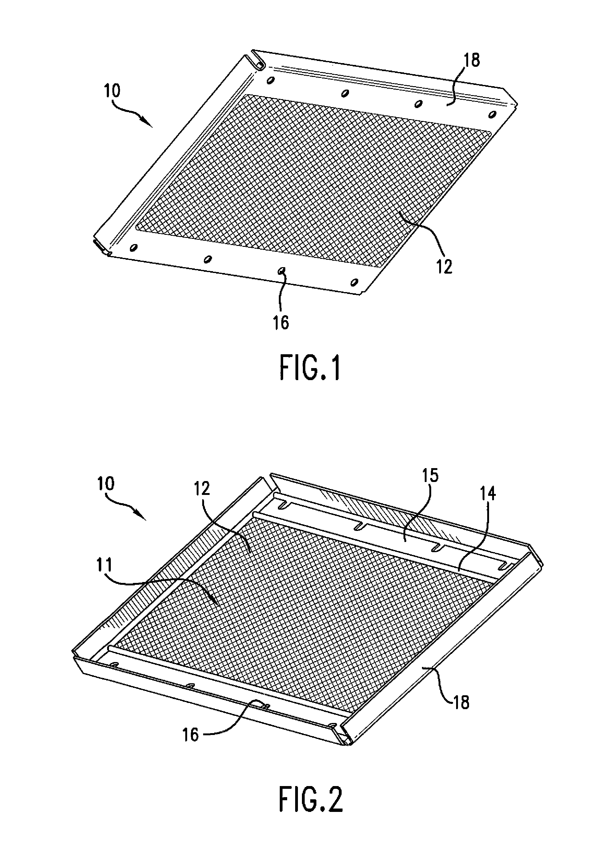
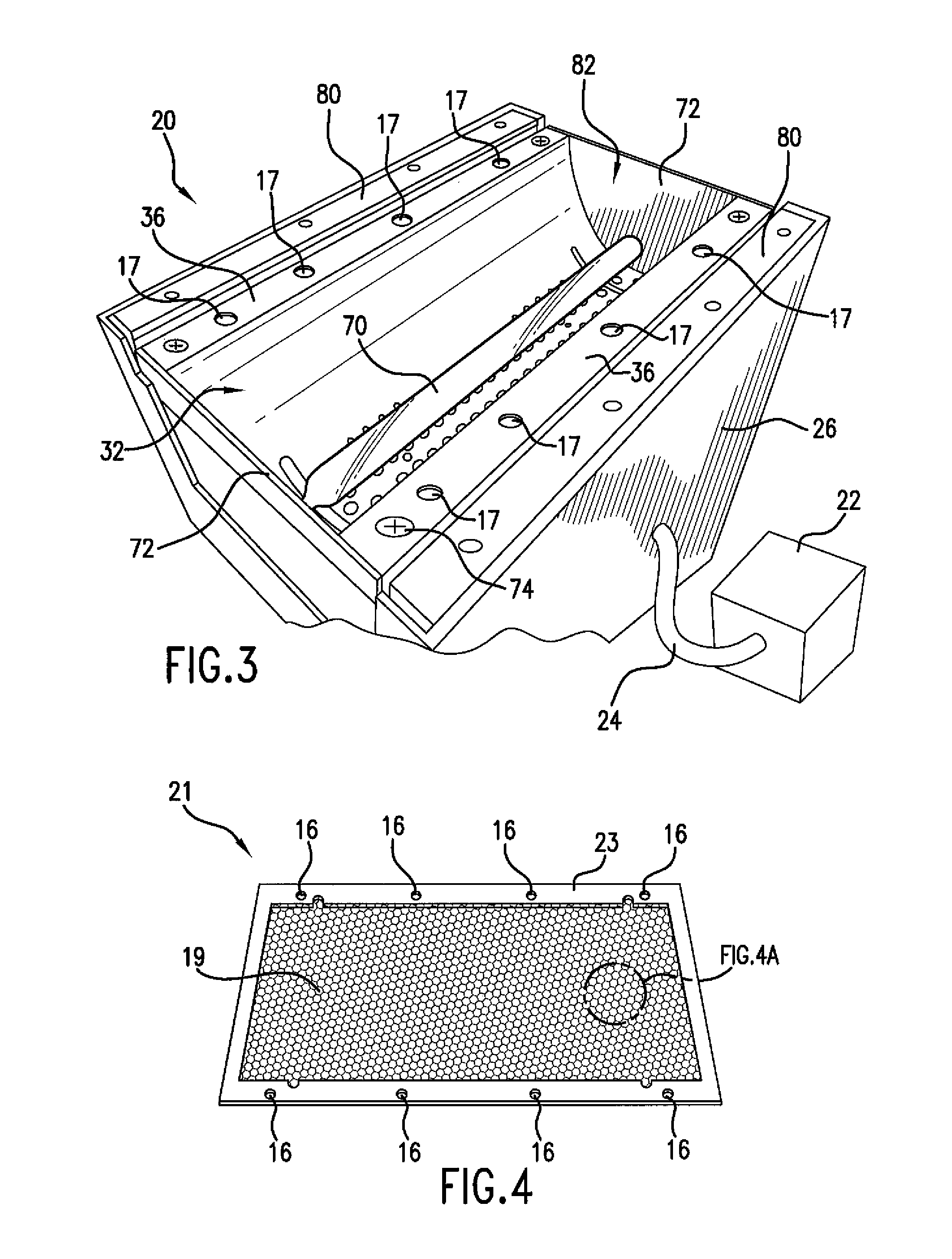
[0037]In a typical microwave UV lamp system 20 (e.g., FIG. 3), an estimated 70% of the UV light produced by the bulb will be reflected by the UV reflector(s) and directed through the RF screen to the object that is being exposed. The remaining 30% of the light from the UV bulb is directed through the RF screen without the aid of the reflector. Of the UV light directed toward the RF screen, a significant amount of light, proportional to the percentage of the area occupied by the mesh will be blocked by the screen. In this Example, the expected light transmission (which corresponds to the open area percentage, or transparency, of the RF screen) of a conventional RF screen formed from fine woven wires (e.g., FIGS. 1 and 2) was computed and compared to the expected light transmission of an RF screen of the present invention with regular hexagonal shaped mesh openings. FIG. 8 illustrates the measurements required to compute the expected light transmission.

Conventional Square Mesh

[0038]Th...

example 2

[0043]One of the benefits of utilizing a mesh pattern with 5 or more nodes was demonstrated. As indicated above, RF screens function as a “faraday cage” in order to block RF energy from escaping. Thus, the amount of RF energy that “leaks” from the RF screen correlates to the largest dimension of the individual mesh openings. The inventors have discovered that the RF screens of the present invention are capable of permitting more light transmission without sacrificing an increase in RF leakage.

[0044]As shown in FIG. 8, the “largest dimension” of the individual openings of a conventional RF screen with square or rectangular mesh is the diagonal (shown as a dashed line LDS). For a square, this dimension can be represented as LDS=√{square root over (2)}(L). In contrast, the “largest dimension” of the individual openings of an RF screen of the present invention utilizing hexagon-shaped openings (shown as dashed line LDH) corresponds to the distance between one node and the corresponding ...


PUM

PropertyMeasurementUnit
Fractionaaaaaaaaaa
Fractionaaaaaaaaaa
Fractionaaaaaaaaaa

Abstract

An RF screen for microwave powered UV lamp systems is provided. The RF screen is formed of a single sheet of conductive material in which a mesh pattern has been formed. The screen includes a non-traditional mesh pattern including individual openings with 3 or more nodes. The RF screen is generally configured to optimize the balance between light transmission and RF energy leakage desired for the particular application. Generally, it is desired that the RF screen has an open area percentage greater than about 80% while limiting RF energy leakage from the microwave powered lamp system to acceptable levels.

Description

FIELD OF THE INVENTION[0001]The present invention is in the technical field of microwave powered UV lamps, and particularly in the technical field of radio frequency (RF) screens utilized in microwave powered UV lamps.BACKGROUND OF THE INVENTION[0002]Ultraviolet (UV) lamp systems may be either microwave power UV lamp systems or medium pressure mercury vapor “ARC” lamp systems. UV lamp systems are used in high speed manufacturing processes to cure inks, coatings, photoresists, and adhesives in a variety of applications. These applications may include, for instance, decorating, laminating, hard-coat protection, circuit board conformal coatings, photoresist, photolithography, photostabilization, printing, and solar simulation. These systems have a wide range of uses and can be used, for example, in the curing of polymers such as photo polymer paints, the curing of inks and coatings, photo activation of adhesives, production of compact discs, and in photo resistant activation. A UV lamp...

Claims


Application Information

Patent Timeline
IPC IPC(8): H01J1/52H05K9/00H05K13/00H05K3/06
CPCH01J65/044Y10T29/49002Y10T29/49156H05K9/0041
Inventor BLANDFORD, III, JOSEPH BERNARD
Owner MILTEC
Why Eureka
Try Eureka