
Method and apparatus for dynamic signal switching of a merging unit in an electrical power system

Active Publication Date: 2011-10-06
ALSTOM GRID UK
View PDF7 Cites 9 Cited by
  • Summary
  • Abstract
  • Description
  • Claims
  • Application Information

AI Technical Summary

Benefits of technology

[0032]A significant advantage of the invention is that only one merging unit is used, and that it is able to combine the inputs from two sources in order to select one output as the best for communicating to connected intelligent electronic devices.
[0033]The combination into a single signal according to certain construction rules (implemented as numerical algorithms) reduces the traffic on the Ethernet, and allows connected intelligent electronic devices which support only one signal source to offer both protection and measurement class functionalities. Without the merging unit having the ability to combine the signals before multicasting, the connected intelligent electronic devices would only have been able to offer protection or measurement accuracy, not both together.
[0034]Those connected intelligent electronic devices can then implement measurement and protection functions. Yet, measurement functions would be provided in prior art protection intelligent electronic devices, but these would be low accuracy measurements for indicative purposes only. For revenue purposes (trading and billing) accuracy requirements would therefore have precluded applications within protection intelligent electronic devices.
[0035]In the present invention, the intelligent electronic devices are receiving a single merged signal which is both accurate enough for all measurement applications, and has the full dynamic range for protection applications, the intelligent electronic devices being able to perform both tasks. This reduces device duplication, and costs.
[0036]The accuracy of the merging unit output at low to moderate currents also improves the accuracy of protection functions which are generally “low-set” (i.e. not related to high short-circuit values), such as generator and motor power protection functions, thermal overload, winding interturn protection, and various forms of earth-fault protection functions on systems with fault current limiting (e.g. resistive earthed systems).

Problems solved by technology

As to higher level fault current flows, the measurement current transformer core may saturate, making its output an erroneous representation of the real primary input.
This cross-site run of current transformer circuits is potentially dangerous, as an inadvertent open circuit could yield dangerous voltages and sparking / arcing in the vicinity of the break.
Further, a space for disposing a large number of electric cables is necessary, and a protection unit and a control unit need to be accommodated in independent cases provided exclusively for the respective units, which has been a cause of the increase in installation space of the devices.
There is no existing solution to allow the input from duplicate (or multiple) measurement sources to combine as a single “optimized” one.
However, no intelligent electronic device on the market today can offer such capability.

Method used


Image

  • Method and apparatus for dynamic signal switching of a merging unit in an electrical power system
  • Method and apparatus for dynamic signal switching of a merging unit in an electrical power system
  • Method and apparatus for dynamic signal switching of a merging unit in an electrical power system

Examples


Embodiment Construction

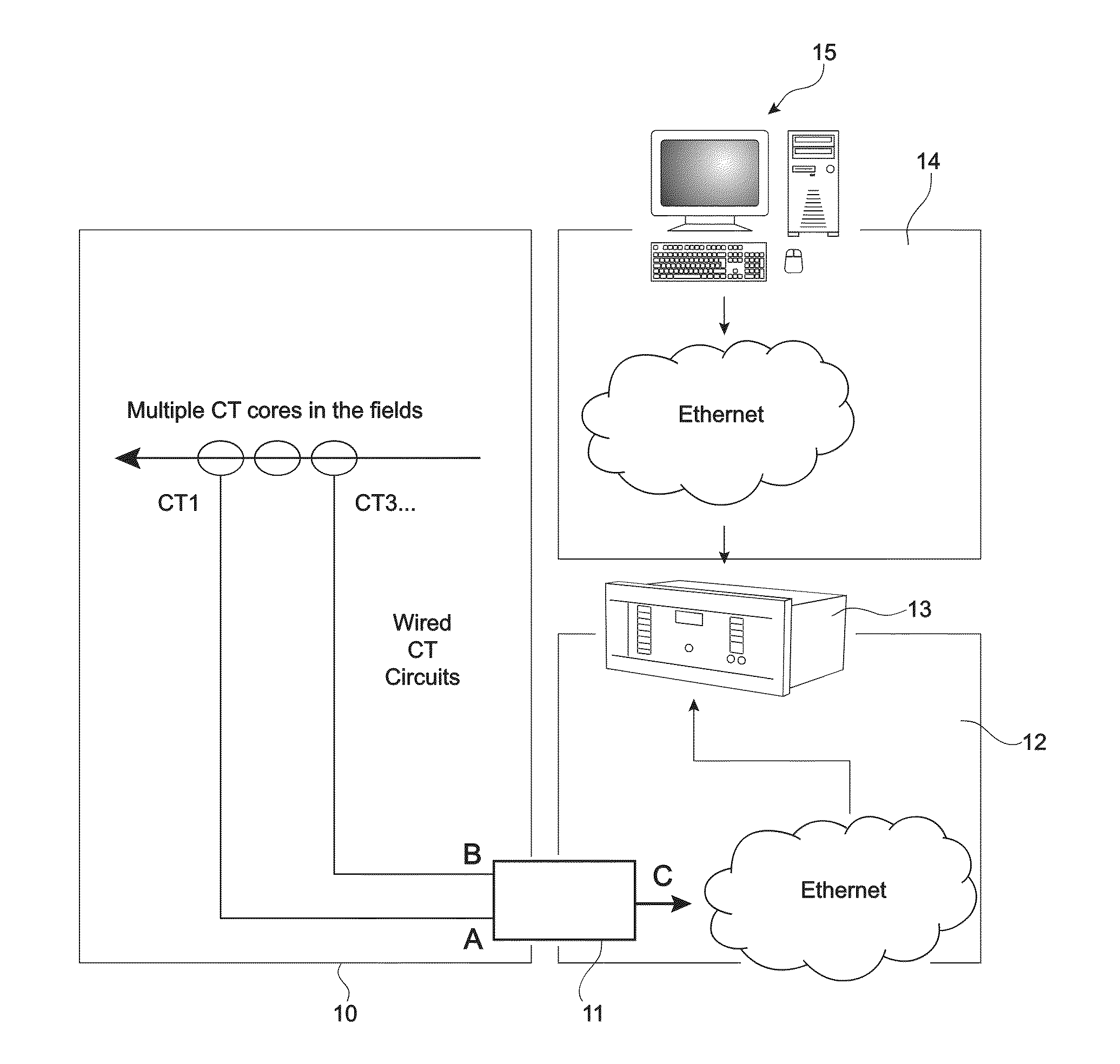
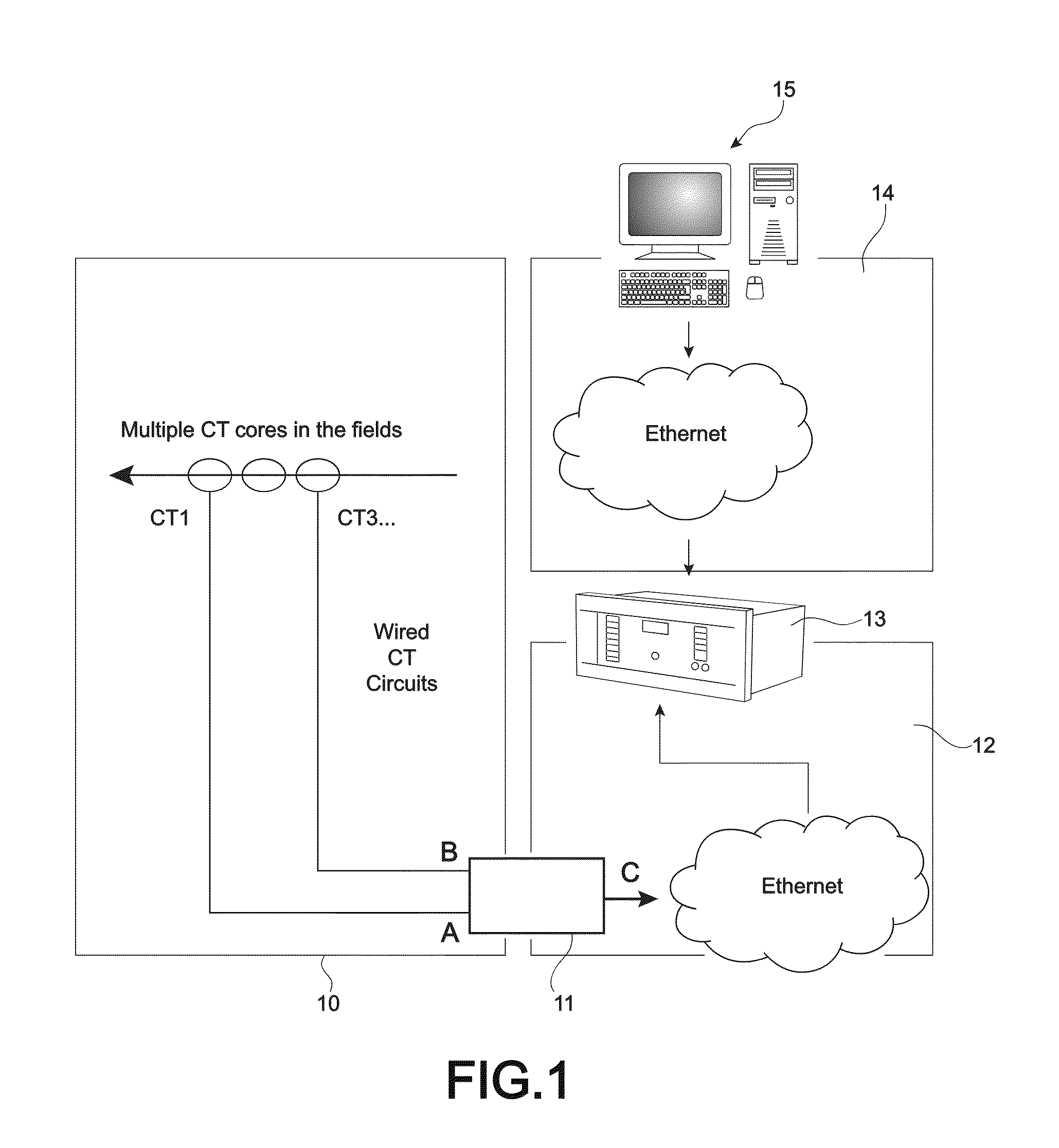
[0043]FIG. 1 shows a typical application, in a single line diagram.

[0044]On said figure are represented:

[0045]a primary interface and hardwiring 10,

[0046]a merging unit 11,

[0047]a process bus 12, for example a IEC 61850-9.2 bus,

[0048]a protection relay 13,

[0049]a station bus 14, for example a IEC 61850-9.2 station bus,

[0050]a control system 15.

[0051]In the invention, the merging unit 11 has two inputs A and B and an output C such that:

[0052]A is a first current input (e.g. from a protection class current transformer core).

[0053]B is a second current input, possibly measurement class.

[0054]C is a combined output of a single stream of measurements, for example IEC 61850-9.2 measurements, based on the real-time best selection from inputs A and B.

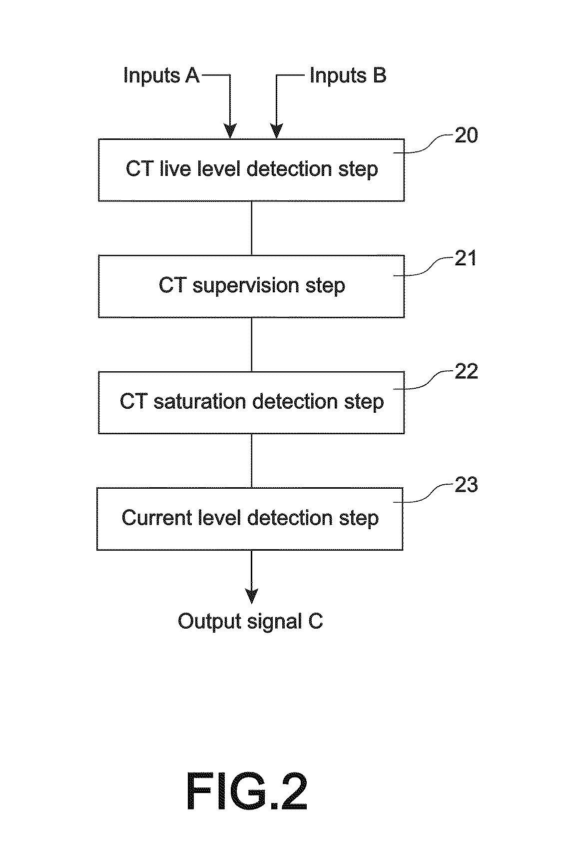
[0055]FIG. 2 shows the steps of the invention process in a preferred embodiment, in which the inputs are inputs A (Protection class inputs as three individual, phase currents) and inputs B (measurement class inputs as three individual, phase cu...


PUM


Abstract

A method and an apparatus for dynamic signal switching with multiple measurement sources, for a merging unit in an electrical power system, said merging unit receiving at least two input signals from at least one current transformer measuring the same physical primary quantity. The method comprises a step of outputting from said merging unit, in a real-time mode, a digitized output stream of sampled values with the truest representation of the physical primary quantity, based on the actual values of the input signals.

Description

BACKGROUND OF THE INVENTION[0001]1. Field of the Invention[0002]This invention relates to a method and an apparatus for dynamic signal switching of a merging unit in an electrical power system.[0003]2. Description of the Related Art[0004]Intelligent electronic devices are installed in electrical power systems to measure the voltage and current flows running through the electrical network. Said intelligent electronic devices may attempt to use these measurements in order to protect the power system against faults or abnormal oscillations, and to allow better control of the power system by human or automatic operators.[0005]Traditionally, such measurements have been made using current and voltage transformers, transforming the power grid quantities into more manageable, safer, lower magnitude scaled quantities for input to intelligent electronic devices.[0006]There is presently a growing trend to digitize the output of such current transformers and voltage transformers, for ease of co...

Claims


Application Information

Patent Timeline
IPC IPC(8): G01R15/18
CPCG01R15/146H02H3/05H02H1/046G01R19/2513
Inventor RICHARDS, SIMON
Owner ALSTOM GRID UK
Learn More