Switching converter systems with isolating digital feedback loops

a technology of digital feedback loop and switching converter, which is applied in the direction of electric variable regulation, process and machine control, instruments, etc., can solve the problems of low bandwidth, high power consumption, and performance of conventional feedback controls, and achieve the effect of limiting elements in modern switching converter systems

Active Publication Date: 2011-10-06
ANALOG DEVICES INC
View PDF16 Cites 32 Cited by
  • Summary
  • Abstract
  • Description
  • Claims
  • Application Information

AI Technical Summary

Problems solved by technology

Feedback control in these converters has typically been accomplished with analog circuits that generally have performance-limiting characteristics, e.g., low bandwidth, high power consumption, and parameter degradation over temperature.
Accordingly, the performance of conventional feedback controls has been found to be a limiting element in modern switching converter systems.

Method used


Image

  • Switching converter systems with isolating digital feedback loops
  • Switching converter systems with isolating digital feedback loops
  • Switching converter systems with isolating digital feedback loops

Examples


embodiment 80

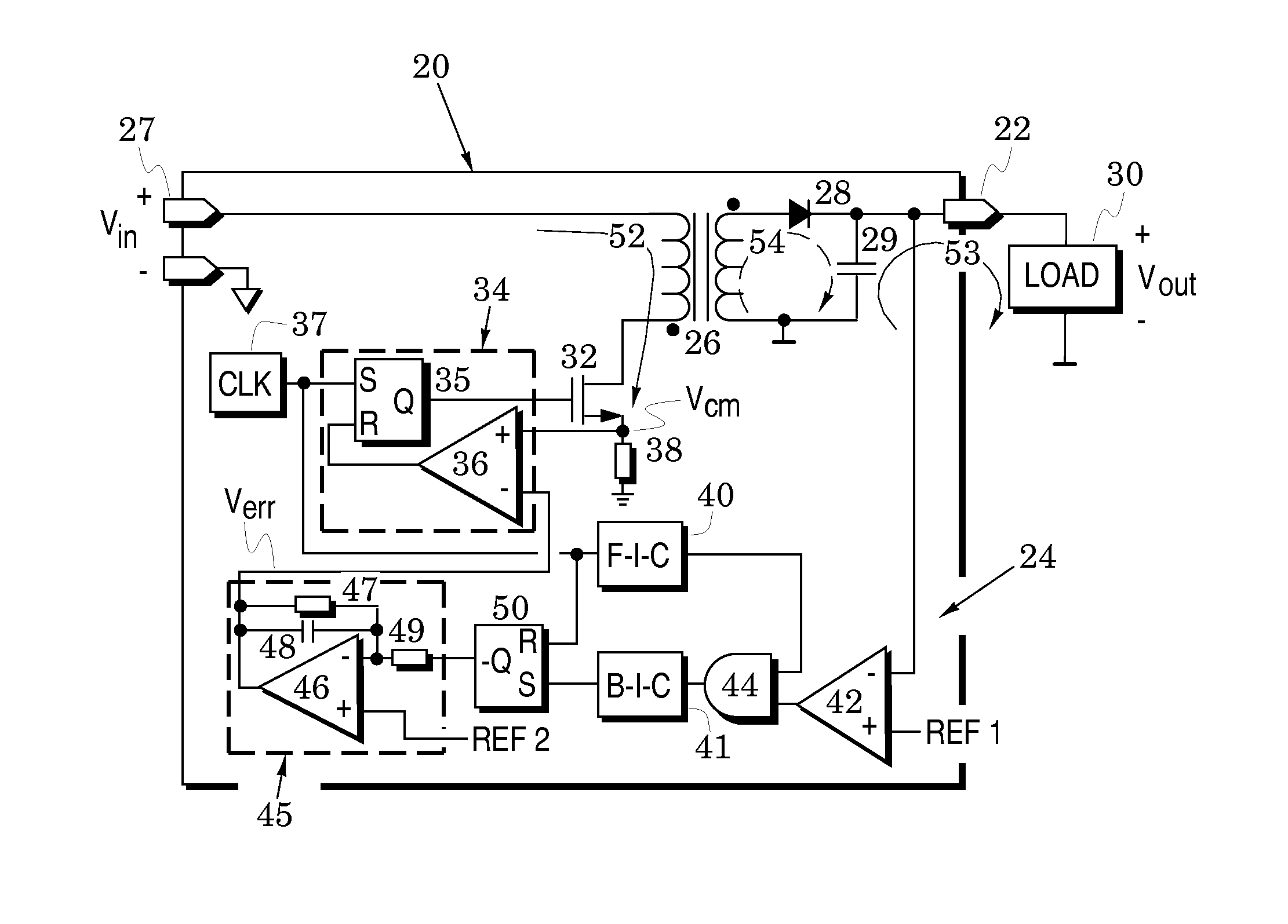
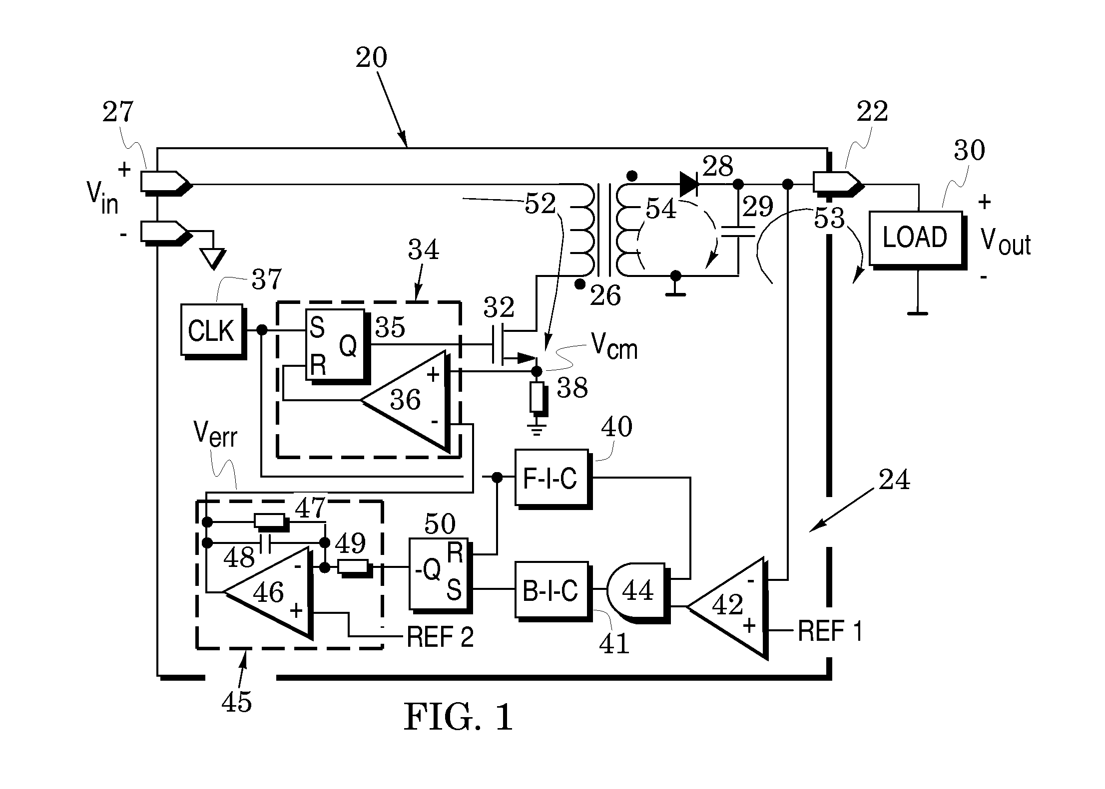
[0033]FIG. 3 illustrates another switching converter system embodiment 80 that includes elements of the system 20 of FIG. 1 with like elements indicated by like reference numbers. In contrast, however, the feedback loop 24 has been modified to a feedback path 84 by replacing the analog error amplifier 45 with a digital up-down counter 85 that is followed by a digital-to-analog converter (DAC) 86 which also receives a reference voltage REF 2. The counter will count up or down on each clock pulse and the direction of the count is determined by the outputs of the flip-flop 50 which is coupled to the up and down ports of the counter. To insure that the count direction command arrives at the counter 85 before the clock pulse to be counted, a time delay 87 is preferably inserted into the clock path before it reaches the counter. In a system embodiment, a proportional-integral-derivative compensator (PID) 88 may be inserted to process the output of the DAC 86.

[0034]In addition, the forward...

embodiment 100

[0042]FIG. 5 illustrates another switching converter system embodiment 100 that includes elements of the system 80 of FIG. 3 with like elements indicated by like reference numbers. In the system 100, the feedback path 84 has been modified to a bidirectional feedback path 104 by replacing the analog comparator 36 with a digital comparator 102 that is driven by the counter 85. In addition, the DAC 86 is replaced by an analog-to-digital converter (ADC) 101 that provides a digital version of the current-mode voltage Vcm to the digital comparator 102. In addition, a primary-side (P-S) state machine 103 replaces the flip-flop 50 and its associated delay 87.

[0043]The clock 37 of the system 80 of FIG. 3 is replaced with a clock 105 that is configured to provide a first clock at a high frequency fb to the P-S state machine 103 in the feedback path and a second clock at a divided-down frequency ff to the flip-flop 35 in the forward path. The second clock can be provided, for example, with a p...

embodiment 120

[0050]FIG. 6 illustrates another switching converter system embodiment 120 in which the input port 27, output port 22, transformer 26, transistor 30, diode 28 and capacitor 29 are arranged as in the systems 20, 80, and 100 of FIGS. 1, 3 and 5. However, the control of the clock 37, clock 105, flip-flop 35 and comparator 36 of those embodiments is represented by a generic controller 122 in the system 120. In addition, the two-way isolation of the F-I-C 40, B-I-C 41, transformer 90, gates 91 and 92, inverters 93 and buffers 94 of those embodiments is represented by a generic isolator 124. Additionally, the decoding of the error amplifier 45, flip-flop 50, counter 85, DAC 86, PID 88, ADC 101, digital comparator 102, and P-S state machine 103 of those embodiments is represented by a generic decoder 126. Finally, the encoding of the comparator 42, gate 44, S-S state machine 106 and comparators 107, 110, 111, 112 and 113 is represented by a generic encoder 128. The isolator 124, decoder 12...


PUM


Abstract

Switching converter systems are provided to control output voltage across a load by means of a converter forward path and a converter feedback path. The forward path preferably includes a transistor, an inductive element, a diode and a capacitor arranged to switchably exchange energy with the capacitor to thereby generate the output voltage. The feedback path preferably extends from the capacitor and is configured to digitally control a duty cycle of the transistor in response to the output voltage. In a system embodiment, the feedback path includes at least one comparator arranged to provide a digital error signal in response to a comparison of the output voltage to a reference voltage; a first isolation channel configured to isolatably transport a clock signal to digitally gate the error signal; a second isolation channel configured to isolatably transport the error signal; and a controller coupled to the first and second isolation channels and configured to control the duty cycle in response to the error signal. A transformer is preferably inserted into the first and second isolation channels to enhance isolation and, preferably, the first and second isolation channels respectively include first and second digital gates that each have an output port coupled to an input port of the other.

Description

BACKGROUND OF THE INVENTION[0001]1. Field of the Invention[0002]The present invention relates generally to switching power converters.[0003]2. Description of the Related Art[0004]Switched-mode voltage converters provide superior power conversion efficiency because they regulate an output voltage or output current with transistor switches that are either on or off so that they never operate in the linear region in which both current and voltage are nonzero. Because at least one of transistor current and voltage is therefore always close to zero, power dissipation is greatly reduced. Because of their high efficiencies, switching converters have been found to be particularly useful in a variety of portable devices (e.g., mobile phones, digital cameras, digital radios, portable disk drives and media players) that are powered by internal batteries (e.g., lithium batteries).[0005]Feedback control in these converters has typically been accomplished with analog circuits that generally have ...

Claims


Application Information

Patent Timeline
Patent Type & Authority Applications(United States)
IPC IPC(8): H02M3/335
CPCH02M3/33523H02M3/33546H02M3/33515
Inventor STRZALKOWSKI, BERNHARD
Owner ANALOG DEVICES INC
Why Eureka
Try Eureka