Method for adaptive blind equalization of PSK signal, equalizer and receiver
a technology of blind equalization and psk signal, applied in the field of optical communication, can solve problems such as inapplicability of the cma to the bpsk signal
- Summary
- Abstract
- Description
- Claims
- Application Information
AI Technical Summary
Benefits of technology
Problems solved by technology
Method used
Image
Examples
first embodiment
The First Embodiment
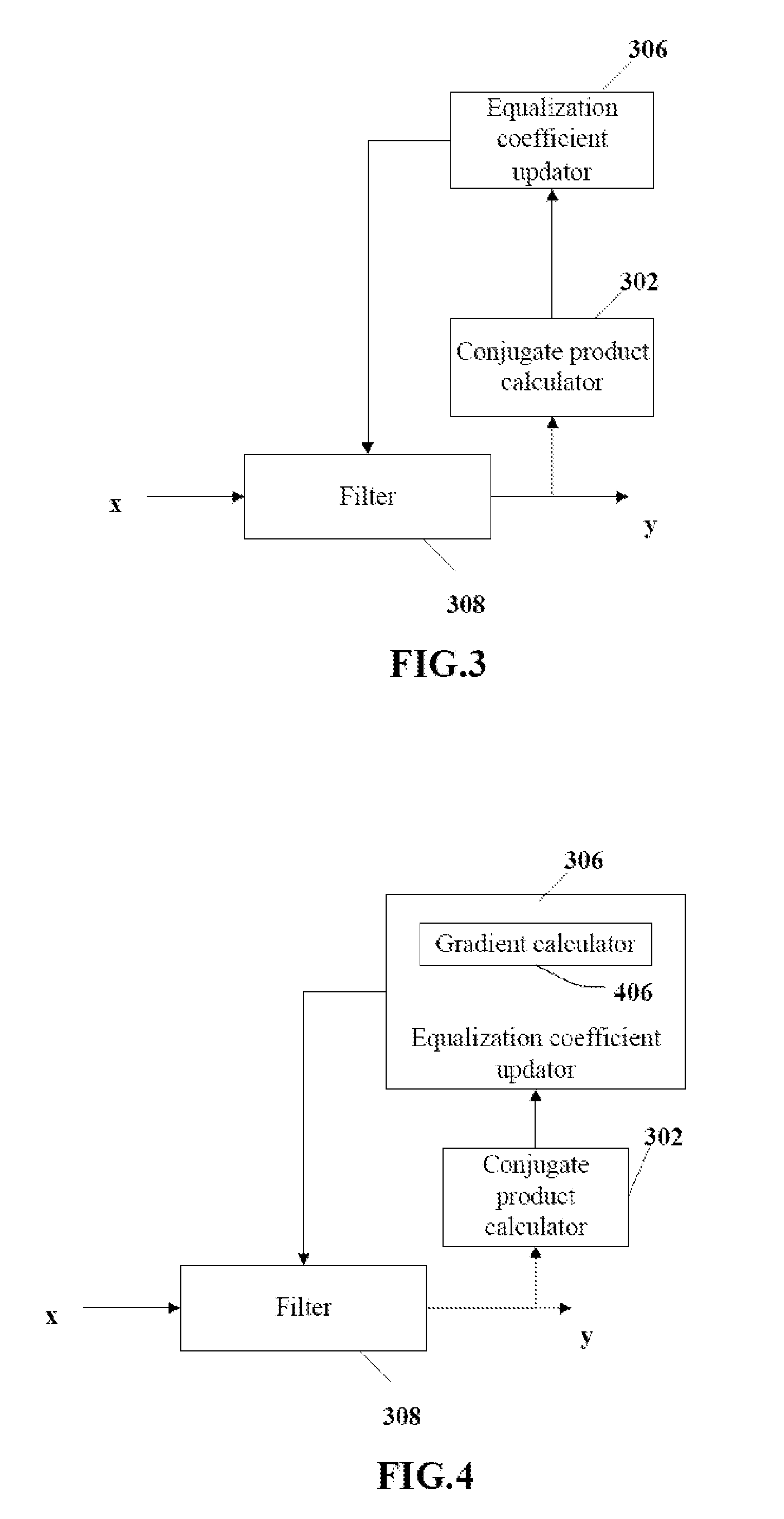
[0026]It is assumed that an adaptive equalizer of a receiver to which a sampled signal is directed be structured as an L-tap FIR filter, where L is an integer larger than or equal to 1 and denotes the number of sampling points to be considered for equalization of the equalizer. Let Xt denote an input signal to the equalizer at a point of time tTs (t is an integer) and Wt denote tap coefficients of the FIR filter at the point of time tTs, so both Xt and Wt are L-dimension vectors. An output of the equalizer at the point of time tTs is yt=WtTXt (T denotes transposition). For example, when L is 3, it means that three samples received consecutively, i.e., Xt=[xts−2,xts−1,xts], where Xt is a current input signal to the equalizer, and xts to xts−2 are three consecutive samples (s is a positive integer denoting the number of samples per symbol), will be considered for equalization of the signal. Although s=2 is typical in a coherent optical communication system, those s...
second embodiment
The Second Embodiment
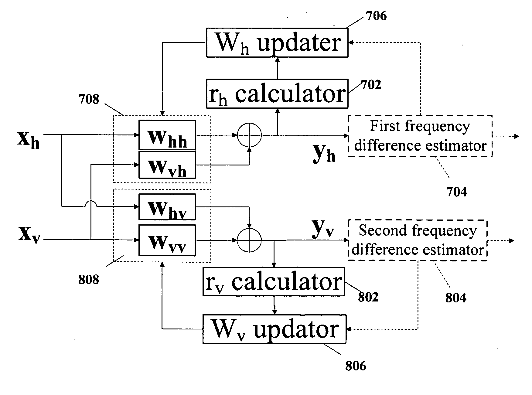
[0048]In a real coherent optical communication system, there is a specific frequency difference Δω between an emitting laser and a local oscillation laser with respective specific line widths Δf. If transmission signal is an mPSK signal, the output yt from the equalizer from which the ISI has been removed completely is an mPSK signal with a frequency difference and phase noise, i.e.:
yt=exp[j(2ktπm+φt+ΔωtTs)],kt=0,1,…m-1.
[0049]Where φt denotes the phase noise, ΔωtTs denotes an additive phase due to the frequency difference between the emitting laser and the local oscillation laser, and Ts denotes a symbol period.
[0050]Correspondingly, an output at a point of time t−1 is:
yt-1=exp[j(2kt-1πm+φt-1+Δω(t-1)Ts)],kt-1=0,1,…m-1.
[0051]The conjugate product of the outputs from the equalizer at the points of time tTs and (t−1)Ts is calculated as rt=ytyt−1* (* denotes conjugation) so that:
rt=exp[j(2ktπm+φt+ΔωtTs)-j(2kt-1πm+φt-1+Δω(t-1)Ts)]
and further that:
rt=exp[j(2kπm+Δφt+Δω...
third embodiment
The Third Embodiment
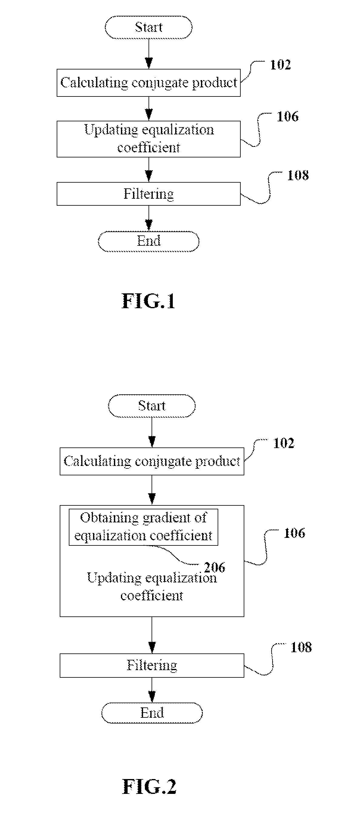
[0061]It has been proposed in the first and second embodiments that the equalization coefficient is updated using the conjugate product of the current output and the precedent output of the equalizer, and the examples of different cost functions applicable to any PSK signal including a BPSK signal have been presented based upon this idea.
[0062]We also know that a BPSK signal is a special PSK signal, and for the equalizer from which the ISI has been removed, the following equation can be derived from the equation (1):
rt≈exp[j(2kπm)]=exp[j(2kπ / 2)]=exp(jkπ),k=0,1.
That is, rt≈±1.
[0063]That is, equalized rt shall be a real number in an ideal scenario without any frequency difference and corresponding to the first embodiment. In other words, its real part shall approximate the modulus of the signal and its imaginary part shall approximate zero. Therefore, the following cost function can further be constructed specifically for a BPSK signal for use in the step 106 of up...
PUM
 Abstract
Description
Claims
Application Information
 - R&D
- Intellectual Property
- Life Sciences
- Materials
- Tech Scout
- Unparalleled Data Quality
- Higher Quality Content
- 60% Fewer Hallucinations
Browse by: Latest US Patents, China's latest patents, Technical Efficacy Thesaurus, Application Domain, Technology Topic, Popular Technical Reports.
© 2025 PatSnap. All rights reserved.Legal|Privacy policy|Modern Slavery Act Transparency Statement|Sitemap|About US| Contact US: help@patsnap.com


