

Electrolyte for a magnesium sulfur battery
a magnesium sulfur battery and electrolyte technology, applied in the field of electrochemical devices, can solve the problems of not being suitable for a cell having a magnesium anode, not being suitable for a cathode material, not being compatible with the electrolyte system,
- Summary
- Abstract
- Description
- Claims
- Application Information
AI Technical Summary
Problems solved by technology
Method used
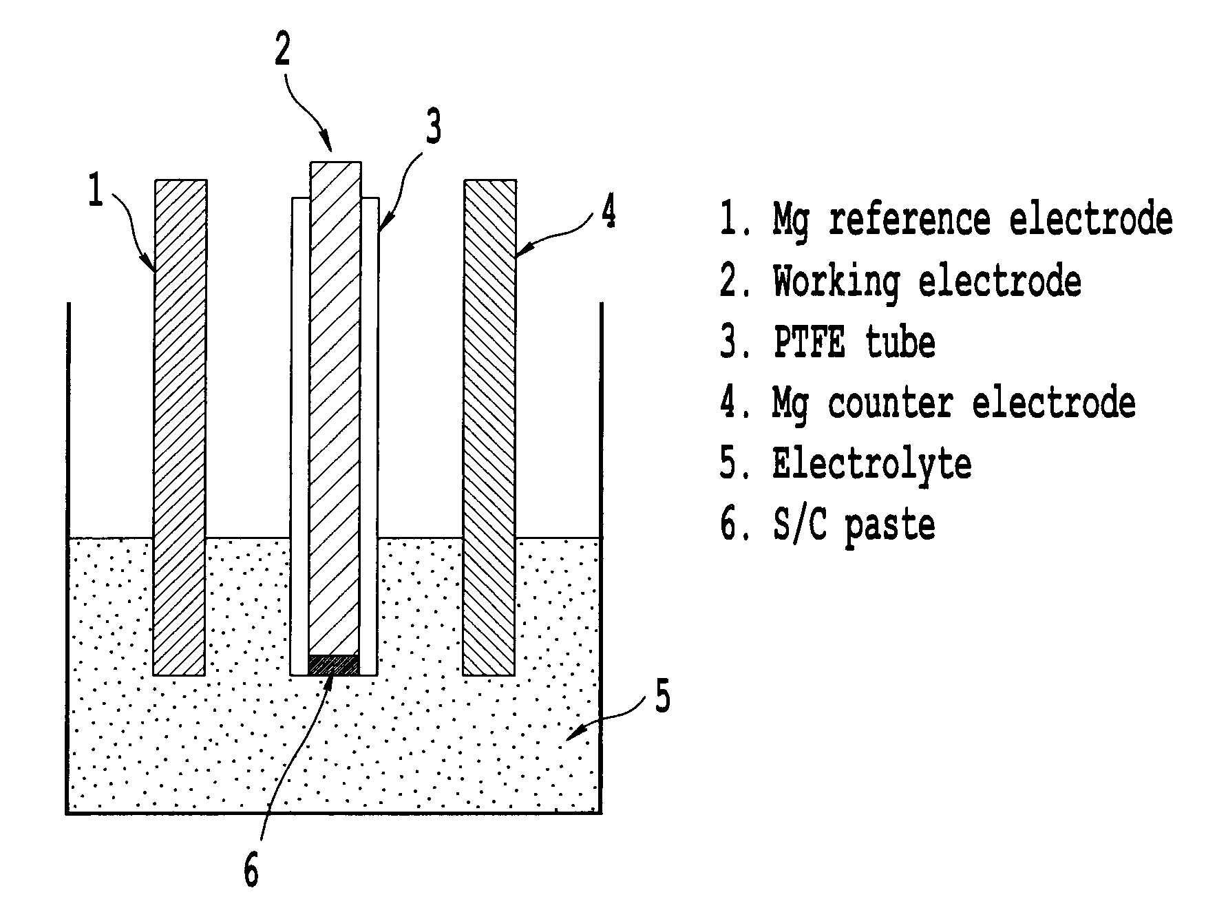
Image

Examples
example 1
[0120]In a glovebox, 1.574 ml of a 1.27 M solution of hexamethyl disalazide magnesium chloride in THF was added to 1.426 ml of dried THF in a screw capped vial. The resulting mixture was rapidly stirred. The solution was then allowed to stand for a few minutes and after standing, 2 ml of 0.5 M AlCl3 (0.5 eq) in THF was added. This mixture was stirred for 48 hours.
example 2
[0121]In a glovebox, 3.17 ml of a 1.27 M solution of bishexamethyl disalazide magnesium in THF was added to 1.426 ml of dried THF in a screw capped vial. The resulting mixture was rapidly stirred. The solution was then allowed to stand for a few minutes and after standing, 2 ml of 0.5 M AlCl3 (0.5 eq) in THF was added. This mixture was stirred for 48 hours.
example 3
[0122]A Mg / S battery was prepared using a test cell (Japan Tomcell). To fabricate the sulfur cathode, a mixture of sulfur and carbon was ball-milled and mixed with water and PTFE resin. The resulting ink was applied to aluminum foil by doctor blade method. The battery was assembled to contain Mg foil as a negative electrode, the sulfur coated aluminum foil as a positive electrode and a glass filter as separator. The electrolyte solutions prepared in Examples 1 and 2 were added to the cell to complete formation of a battery. A discharge test of the battery was conducted at a constant current of 50 μA till the battery voltage was lowered to 0.1V. The discharge capacity of the battery was measured to be 241 mAh / g.
PUM
| Property | Measurement | Unit |
|---|---|---|
| voltage | aaaaa | aaaaa |
| energy density | aaaaa | aaaaa |
| energy density | aaaaa | aaaaa |
Abstract
Description
Claims
Application Information