Optical Transmitter and Optical OFDM Communication System

a communication system and optical fiber technology, applied in the field of optical transmitters and optical fiber communication systems, can solve the problems of inability to extract accurate distortion components, halve the transmission capacity of one optical fiber, etc., to reduce the distortion of the reception signal, increase the transmission capacity, and reduce the deterioration of the receiving sensitivity

Inactive Publication Date: 2011-10-13
HITACHI LTD
View PDF22 Cites 61 Cited by
  • Summary
  • Abstract
  • Description
  • Claims
  • Application Information

AI Technical Summary

Benefits of technology

[0082]According to the present invention, it is possible to provide an optical transmitter that can reduce distortion of a reception signal caused by inter-subcarrier interference without any influence of noise in a transmission channel or a receiver, and can reduce deterioration of a receiving sensitivity in an optical OFDM communication system using a direct detection receiving system, and the optical OFDM communication system. Moreover, according to the present invention, it is possible to conduct communication while keeping a spectrum bandwidth of an optical OFDM signal to an original signal bandwidth B. Thus, it is possible to increase a transmission capacity that can be communicated by one optical fiber twice as large as a related-art optical OFDM communication system using a guard band when realizing a wavelength division multiplexing communication system using the above technique. Still further, according to the present invention, there is an advantage that can reduce an influence of the inter-subcarrier interference caused by photoelectric conversion not depending on an individual variability in the characteristics of devices used in the optical OFDM communication system, such as a photodiode, an optical modulator, a driver amplifier, or a preamplifier, a characteristic change attributable to a change in the environments such as temperature, and a change with time and, it is possible to be widely and generally applied.

Problems solved by technology

As a result, when the optical OFDM transmission technique is applied to a wavelength division multiplexing system, there arises such a problem that a total transmission capacity that can be transmitted by one optical fiber is halved.
Also, in the above fourth technique, because the distortion component attributable to the inter-subcarrier interference is extracted from a signal obtained by demodulating the reception signal, there arises such a problem that the distortion component is extracted with the use of a false demodulated signal caused by noise, and an accurate distortion component cannot be extracted.

Method used


Image

  • Optical Transmitter and Optical OFDM Communication System
  • Optical Transmitter and Optical OFDM Communication System
  • Optical Transmitter and Optical OFDM Communication System

Examples


first embodiment

1. First Embodiment

[0100]A first embodiment will be described with reference to FIG. 1. In this example, for description, it is assumed that modulation of subcarriers is 4-QAM. However, this embodiment is not limited to this modulation, but is applicable to an arbitrary subcarrier modulation system. Also, it is assumed that the number of subcarriers is N (N is an integer).

[0101]FIG. 3 illustrates a configuration diagram of an optical OFDM communication system.

[0102]The optical OFDM communication system includes, for example, a transmitter (optical transmitter) 1, an optical fiber 5, and a receiver (optical receiver) 6. The transmitter 1 includes, for example, a transmission signal processor 100, a driver amplifier 2, a laser 3, and an optical modulator 4. The transmitter 1 may include an input terminal 9. The receiver 6 includes, for example, a photodiode 7, a preamplifier 8, and a reception signal processor 200. The receiver 6 may include an output terminal 10. The transmitter 1 an...

second embodiment

2. Second Embodiment

[0115]A second embodiment will be described with reference to FIG. 7. FIG. 7 illustrates a configuration diagram of the transmission signal processor 100 of the transmitter 1 according to the second embodiment. The same configurations as those in the first embodiment are denoted by identical reference symbols, and their description will be omitted. The overall configuration of the system is identical with those of the first embodiment.

[0116]The transmission signal processor 100 according to this embodiment further includes a distortion generator 170′ and subtractors 310. In this embodiment, the distortion generator 170 used in the first embodiment is used twice (distortion generators 170 and 170′ in FIG. 7). The distortion generators 170 and 170′ can have the same configuration. A residual distortion (corresponding to a term of |c2|2 / |c0|2 on a right side of the above Formula (10)) attributable to the inter-subcarrier interference, which cannot be removed by the ...

third embodiment

3. Third Embodiment

[0119]A third embodiment will be described with reference to FIGS. 13 and 17. The overall configuration of the system is identical with that of the first embodiment. The same configurations as those in the first embodiment are denoted by identical reference symbols, and their description will be omitted.

[0120]FIG. 13 illustrates a configuration diagram of a transmission signal processor according to the third embodiment.

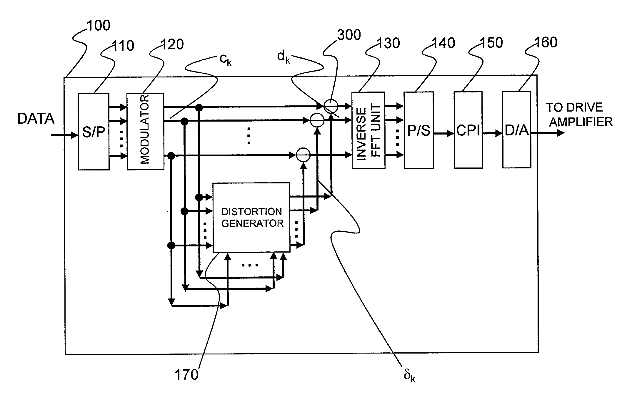
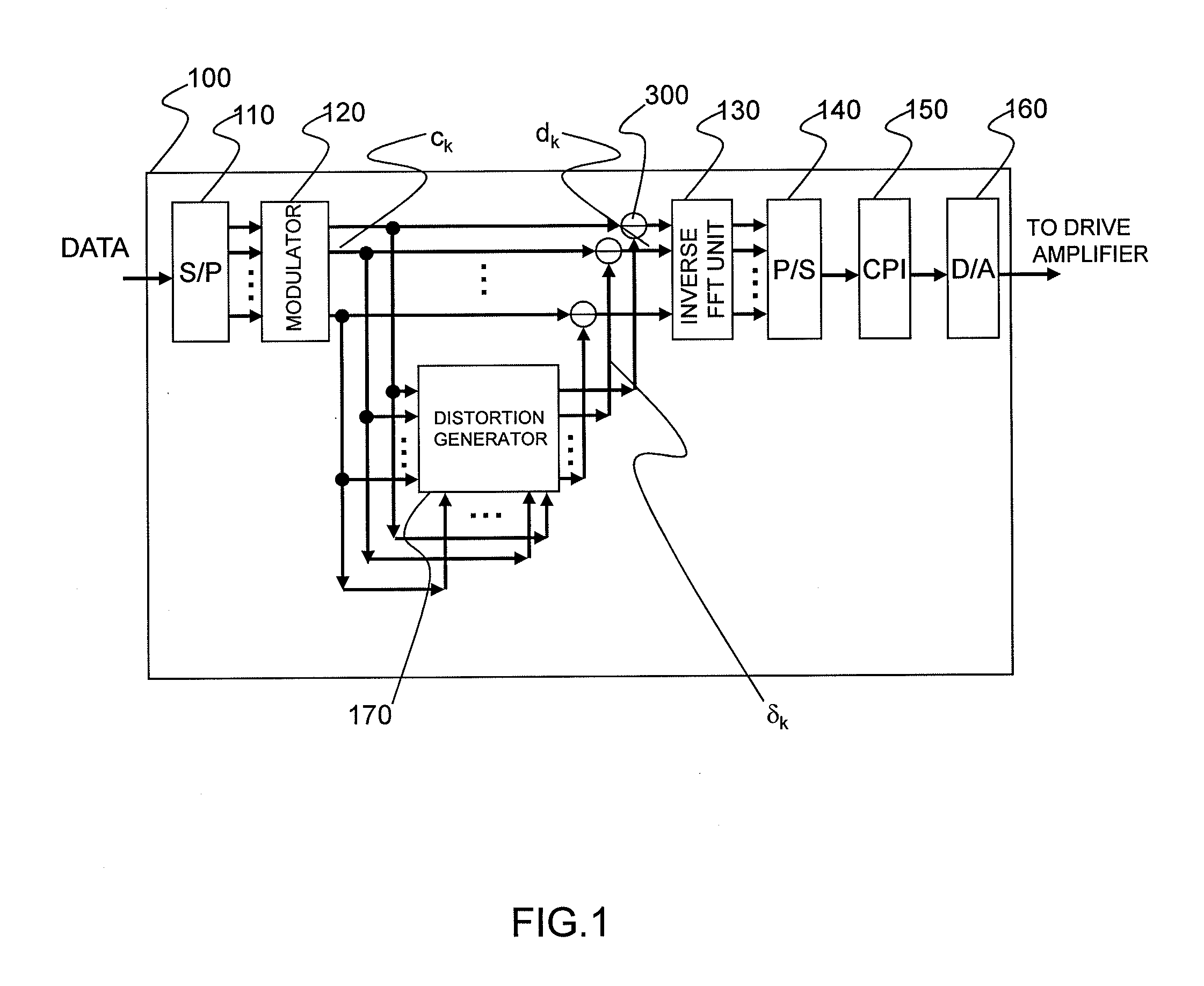
[0121]The transmission signal processor 100 according to the third embodiment includes, for example, the serial-parallel converter (S / P) 110, the subcarrier modulator 120, the inverse FFT unit 130, the parallel-serial converter (P / S) 140, the cyclic prefix insertion unit (CPI) 150, the digital-analog converter (DA converter) 160, a predistortion unit 180, 2:1 switches (first switches) 181 and 1:2 switches (second switches) 182 corresponding to the subcarriers, and a switch controller 190.

[0122]FIG. 14 is a configuration diagram of the predistortion...


PUM


Abstract

Distortion of a reception signal which is attributable to interference between subcarriers during photoelectric conversion is reduced in an optical OFDM communication system without broadening the signal band. A transmission signal processing unit (100) in a transmitter is provided with a distortion generating circuit (distortion generating unit) (170). A subcarrier signal is utilized as an input signal for the circuit. The distortion generating circuit (170) generates a baseband OFDM signal by means of inverse FFT calculation using the input signal, computes the square of the absolute value of the signal, and restores the subcarrier signal by mean of FFT calculation. Because interference between subcarriers is also included in the signal, the distortion element generated by the interference between the subcarriers can be extracted when the difference from the input signal is found. The signal obtained by subtracting the distortion element from the subcarrier signal, which has been modulated using the original data to be communicated, is used as the transmission signal. The transmission signal is photoelectrically converted with a receiver. The interference between subcarriers generated at this time is smaller than when the aforementioned processing is not performed.

Description

FIELD OF THE INVENTION[0001]The present invention relates to an optical transmitter and an optical OFDM communication system, particularly to an optical transmitter in an optical communication system using a multicarrier, and more particularly to an optical transmitter and an optical OFDM communication system, which reduce an influence of interference between subcarriers in an optical orthogonal frequency division multiplexing (OFDM) communication system using a direct detection receiving system.BACKGROUND OF THE INVENTION[0002]In an optical communication system put into practical use up to now, a two-level modulation and demodulation technique using light intensity is utilized. Specifically, “0” and “1” of digital information are converted into on-off of intensity of a light at a transmitter side, and transmitted into an optical fiber. The light that has propagated through the optical fiber is subjected to photoelectric conversion at a receiver side to restore original information....

Claims


Application Information

Patent Timeline
Patent Type & Authority Applications(United States)
IPC IPC(8): H04B10/04H04B10/00H04B10/516
CPCH04J14/02H04L25/03343H04B10/548H04L27/2626H04L27/2697H04L25/03821
Inventor SASAKI, SHINYA
Owner HITACHI LTD
Why Eureka
Try Eureka