
Methods and Compositions for High-Resolution Micropatterning for Cell Culture

Inactive Publication Date: 2011-10-13
RGT UNIV OF CALIFORNIA
View PDF2 Cites 13 Cited by
  • Summary
  • Abstract
  • Description
  • Claims
  • Application Information

AI Technical Summary

Benefits of technology

[0012]Embodiments of the invention are directed to methods for producing a new type of reliable, low-cost cell culture platform

Problems solved by technology

However, many current micropatterning techniques, such as those based on cell-resistant poly-ethylene-glycol (PEG) molecular monolayers, have not consistently produced high degrees of cellular compliance to desired patterns and often have difficulty producing patterns that can be maintained for more than a few days during culture.
These limitations may be due to the fundamental fragility of molecular monolayers, often vulnerable to hydrolytic cleavage, as well as the difficulty in producing close-packed molecular arrangement and continuous coverage over an entire surface.
Beyond proof-of-concept demonstrations of cell patterning, such micropatterning schemes therefore have not been successfully introduced as products widely adopted by the research community in biology despite the diverse benefits of cell micropatterning.
One unaddressed barrier to enhanced research productivity using neuronal cell cultures is the disorganized distribution and random arrangement of neurons and their axons in conventional, unpatterned culture dishes.
While neuroscientists have developed imaging and image processing capabilities to improve experimental throughput, many of these solutions are expensive to implement and do not directly address the challenges of locating and distinguishing individual neurons in a disorganized culture.

Method used


Image

  • Methods and Compositions for High-Resolution Micropatterning for Cell Culture
  • Methods and Compositions for High-Resolution Micropatterning for Cell Culture
  • Methods and Compositions for High-Resolution Micropatterning for Cell Culture

Examples


example 1

Process Overview

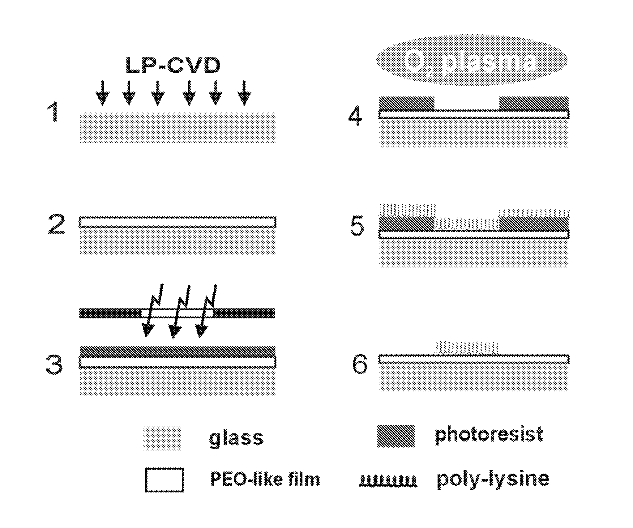
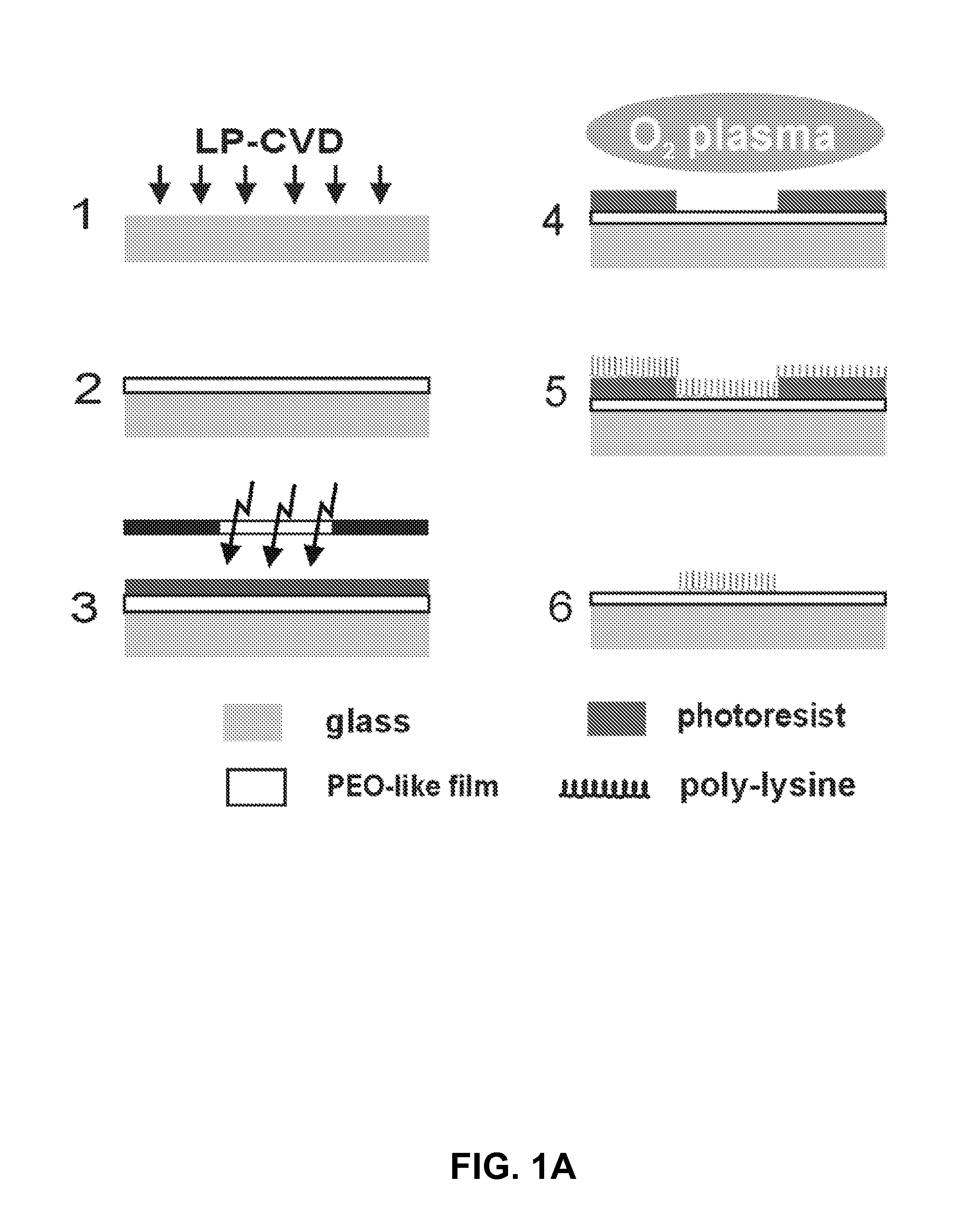
[0072]This example provides an overview of a process for creating used to create poly-lysine micropatterns on the surface of a glass substrate. The glass substrate (usually a 4″ Pyrex wafer (Pyrex 7740, double-side polished, University Wafer, Boston, Mass.) was positioned on the lower, ground electrode of a parallel plate plasma system. As diagrammed in FIG. 1A(1), process gas, comprising 20% vapors of diglycol methyl ether (CAS#111-96-6, J. T. Baker, Phillipsburg, N.J.)] (“diglyme”) in argon (Ar) was introduced into the chamber at a total pressure of ˜20 mT. An RF generator (Plasma-Therm PK-12, Plasmatherm LLC, St. Petersburg, Fla.) was used to induce a plasma using a power of approximately 1-2 W. Under these conditions, the diglyme molecules polymerized to form a PEO-like, solid material that deposited uniformly on the glass substrate as shown in FIG. 1A(2). The substrate, after being blanketed with the PEO-like film then underwent standard photolithography. Photor...

example 2

Oxygen Plasma

[0074]Oxygen plasma. Pyrex samples with deposited film were treated with oxygen plasma using a March Plasmod plasma system (March Plasma System, Concord, Calif.). Surfaces were treated at 25° C. with 20 W of oxygen plasma for 15 sec. at ˜1.3 T. The duration of the oxygen plasma was limited to avoid eroding the photoresist and distorting the lithographic pattern.

example 3

Contact Angle

[0075]Contact angle. The wetability of water on the PEO-like film was measured using a Kruss Contact Angle Measuring System (Kruss GmbH, Hamburg, Germany). Contact angles were determined from magnified images of sessile drops of ˜10 μL deposited on the film surface with a miniature syringe. Numerous drops were measured for each sample, and data represent an average of at least 10 measurements.


PUM

PropertyMeasurementUnit
Temperatureaaaaaaaaaa
Lengthaaaaaaaaaa

Abstract

Composite structures and methods for generating micropatterned materials suitable for use in cell culture applications are disclosed. The improvement of these compositions and methods over the prior art is based on the unexpected discovery that minor chemical modifications can be introduced to greatly enhance the adherence and / or stability of a cell-adhesive material. The micropatterned materials are inexpensive to manufacture, have long shelf-life, and are stable for prolonged periods of time under cell-culture conditions. Moreover, biologists can use these micropatterned substrates with the same ease as conventional cultureware and without the need for special sample preparation.

Description

CROSS REFERENCE TO RELATED APPLICATIONS[0001]This application claims the benefit of U.S. Provisional Application No. 61 / 102,071, filed Oct. 2, 2008, the entire disclosure of which is hereby incorporated by reference in its entirety for all purposes.STATEMENT REGARDING FEDERALLY SPONSORED RESEARCH OR DEVELOPMENT[0002]Not applicable.BACKGROUND OF THE INVENTION[0003]1. Field of the Invention[0004]The invention relates to the fields of biology, cell culture, biochemistry, and lithography.[0005]2. Description of the Related Art[0006]The micropatterning of cells along micron-scale features has enabled broad experimental capabilities for diverse applications in basic research, regenerative medicine, tissue engineering, as well as diagnostics and screening. See, e.g., Andersson, H.; van den Berg, A., Microtechnologies and nanotechnologies for single-cell analysis. Curr Opin Biotechnol 2004, 15, (1), 44-9, Bashir, R., BioMEMS: state-of-the-art in detection, opportunities and prospects. Adv D...

Claims


Application Information

Patent Timeline
IPC IPC(8): C12N5/079B32B3/00B32B7/12C12N5/071C12N5/02
CPCC12M25/00C12M35/08C12N5/0068Y10T428/2878C12N2535/10Y10T428/28Y10T428/24479C12N11/02
Inventor CHANG, WESLEY C.
Owner RGT UNIV OF CALIFORNIA
Learn More