Touch Sensitive Holographic Displays
- Summary
- Abstract
- Description
- Claims
- Application Information
AI Technical Summary
Benefits of technology
Problems solved by technology
Method used
Image

Examples
Embodiment Construction
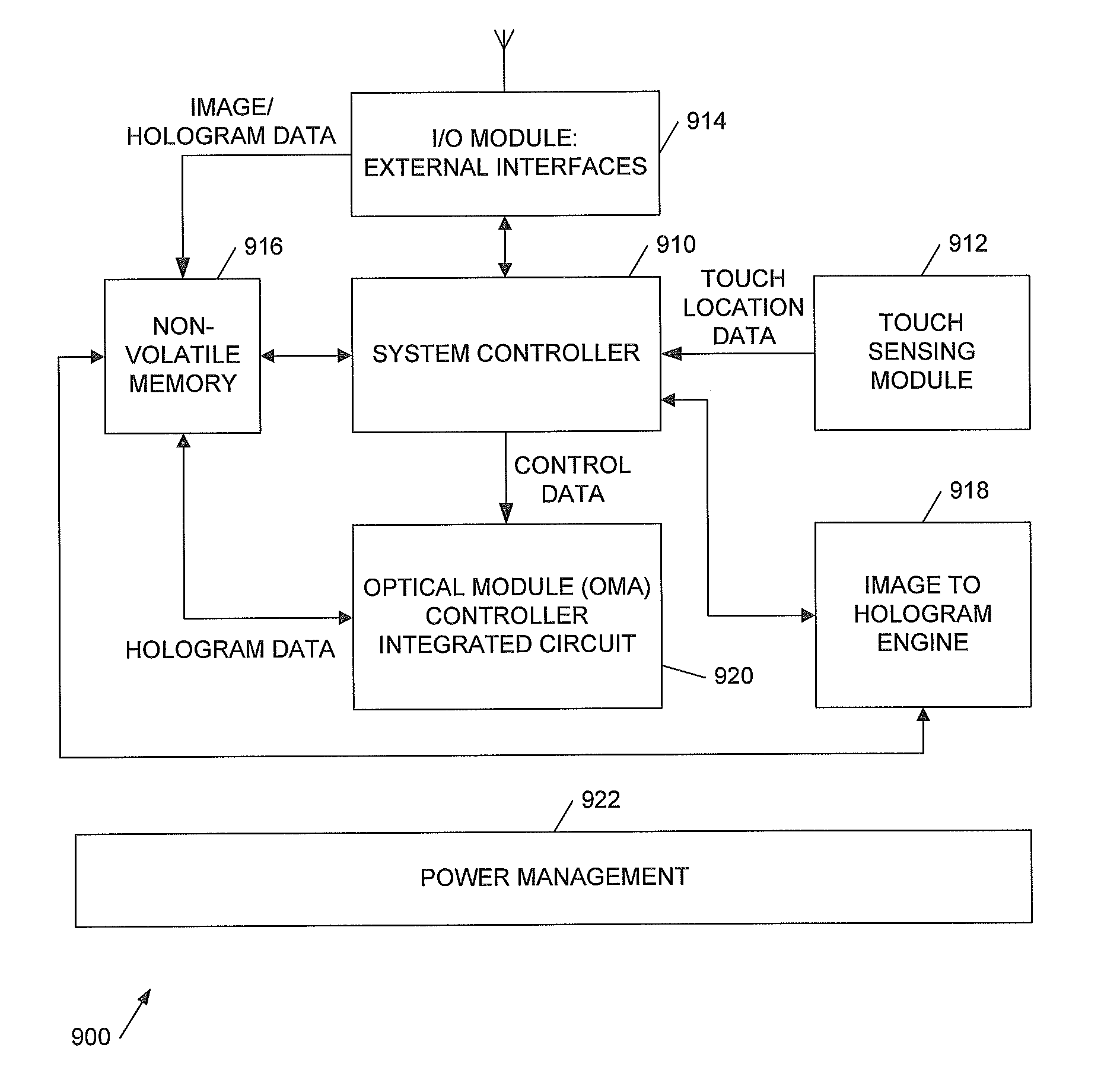
[0049]This invention relates to touch sensitive holographic image display systems, in particular to systems which are able to project onto a surface at an acute angle. The invention also provides related methods and corresponding processor control code.
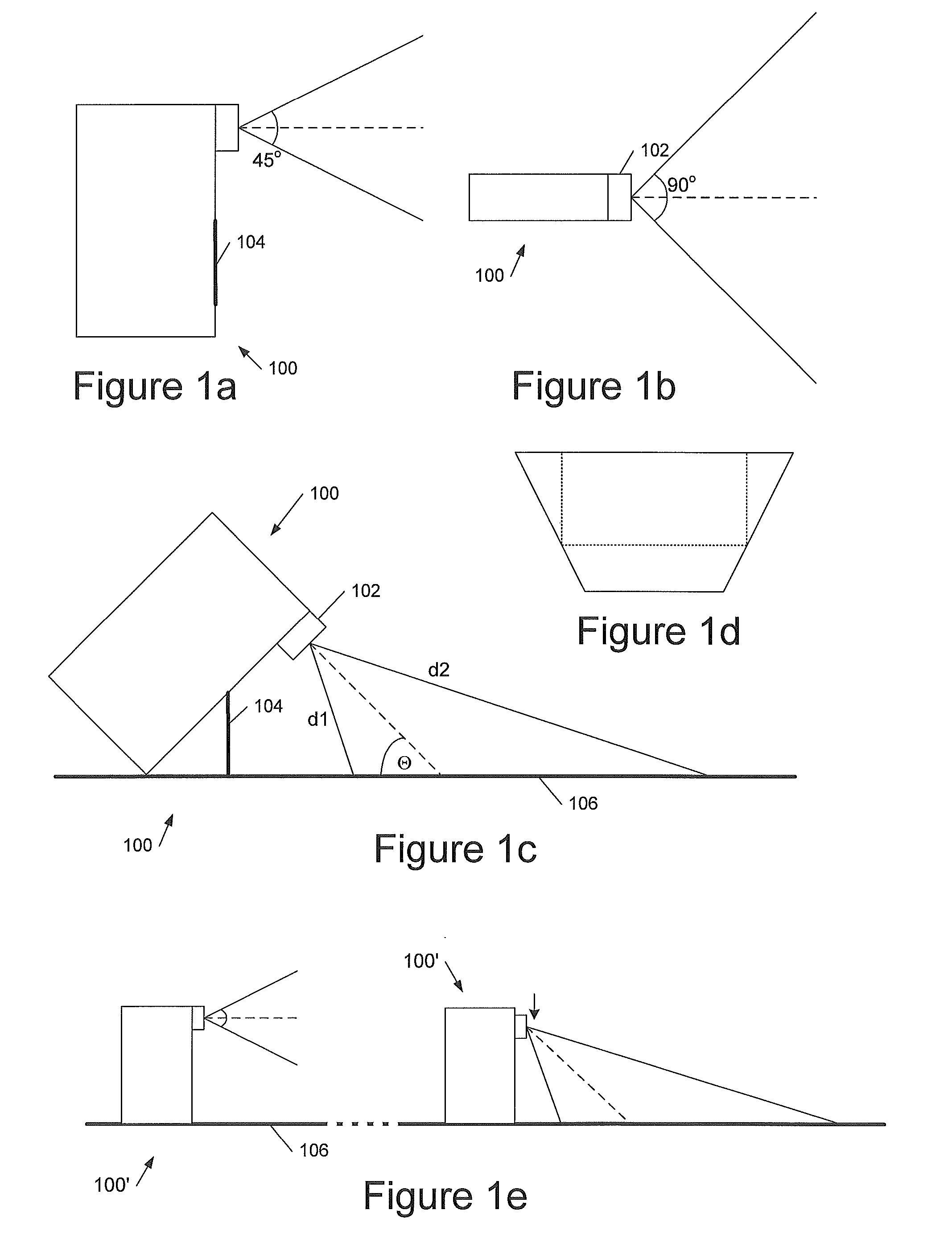
[0050]Referring to FIG. 1a, this shows a side view of an embodiment of a holographic image projection device 100 having 2 configurations, the first configuration in which the device projects forwards, and a second configuration (shown in FIG. 1c) in which the device projects outwards and downwards onto a surface 106 such as a table-top. The device includes an output lens 102 and a foldable stand, for example a bipod stand 104 to support the device in its table-down configuration. In some preferred embodiments the foldable support 104 or some similar mechanism supports the device at a known angle to the surface 106 in its table-down configuration, which has the advantage that the degree of keystone distortion is also known and can ther...
PUM
 Abstract
Description
Claims
Application Information
 - R&D
- Intellectual Property
- Life Sciences
- Materials
- Tech Scout
- Unparalleled Data Quality
- Higher Quality Content
- 60% Fewer Hallucinations
Browse by: Latest US Patents, China's latest patents, Technical Efficacy Thesaurus, Application Domain, Technology Topic, Popular Technical Reports.
© 2025 PatSnap. All rights reserved.Legal|Privacy policy|Modern Slavery Act Transparency Statement|Sitemap|About US| Contact US: help@patsnap.com